Mazda 3 Service Manual: Airflow Mode Actuator Removal/Installation [Full Auto Air Conditioner]
1. Set the air intake mode to FRESH.
2. Set the air mix mode to MAX COLD.
3. Disconnect the negative battery cable..
4. Remove the following parts:
a. Front doors.
b. Front scuff plate.
c. Front side trim.
d. Dashboard under cover.
e. Glove compartment.
f. Upper panel.
g. Shift lever knob (MTX).
h. Selector lever knob (ATX).
i. Shift panel.
j. Side wall.
k. Console.
l. Shift lever component (MTX).
m. Selector lever component (ATX).
n. Hood release lever.
o. Lower panel.
p. Knee bolster.
q. Driver-side air bag module.
r. Steering wheel.
s. Column cover.
t. Combination switch.
u. Joint cover.
v. Steering shaft.
w. Center panel.
x. Audio unit.
y. Climate control unit.
z. Instrument cluster.
aa. Center cover.
ab. Dashboard upper panel.
ac. Hole cover.
ad. Information display.
ae. A-pillar trim.
af. Front fender molding.
ag. Windshield wiper arm and blade.
ah. Cowl grille.
ai. Windshield wiper motor.
aj. Rear heat duct (1).
ak. Shower ducts.
al. Heater case.
5. Remove the nuts and bolts for installing the dashboard to the body.
6. Remove the nuts and bolts for installing the A/C unit to the dashboard.
7. Remove the accelerator pedal..
8. Disconnect the following connectors:
-
Blower motor connector
-
Power MOS FET connector
-
Evaporator temperature sensor connector
-
Air intake actuator connector
-
Air mix actuator connector
-
Airflow mode actuator connector
9. Remove the dashboard..
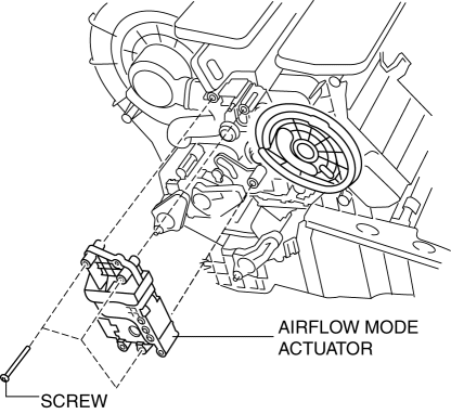
10. Remove the airflow mode rod from the airflow mode actuator.
11. Remove the screw.

12. Remove the airflow mode actuator..
13. Install in the reverse order of removal.
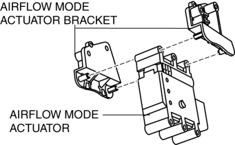
Airflow Mode Actuator Disassemble Note
1. Remove the airflow mode actuator bracket as shown in the figure.

 Airflow Mode Actuator Inspection [Full Auto Air Conditioner]
CAUTION:
If the lever position exceeds the operation range shown in the figure, the
circuit in the actuator could be damaged. Always perform an actuator operation
inspection with the lev ...
 Ambient Temperature Sensor Inspection [Full Auto Air Conditioner]
1. Measure the temperature around the ambient temperature sensor and measure
the resistance between the ambient temperature sensor terminal.
If the characteristics of the ambient tempera ...
Other materials:
Lights-On Reminder
The lights-on reminder is operable when
the time setting *1 of the auto headlight off
function is off.
If lights are on and the ignition is switched
to ACC or the ignition is switched off, a
continuous beep sound will be heard when
the driver's door is opened.
*1 If the light switch is le ...
Applications
NOTE
Depending on the grade and specification,
the screen display may differ.
Select the icon on the home screen to
display the Applications screen. The
following information can be verified.
Top screen
Item
Function
HD
Radio™
Traffic
Map
—
...
Gps Antenna Feeder Inspection
With Audio Unit (Without Display)
1. Verify that the continuity is as indicated in the table.
If not as indicated in the table, replace the GPS antenna feeder.
With Audio Unit (With Display)
NOTE:
GPS antenna feeder is integrated with the antenna feeder No.4.
1. ...
