Mazda 3 Service Manual: Side Step Molding Removal
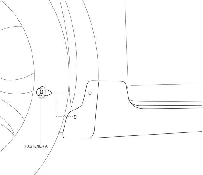
1. Remove the fasteners A.
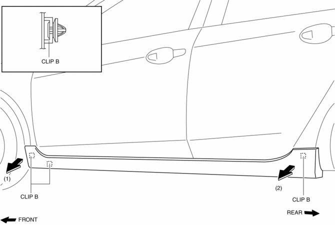
2. Using the removal tool, disengage clips B in the direction of the arrow (1), (2) shown in the figure.
NOTE:
-
Leave the disengaged clip B in place in consideration of the servicing.
3. Slide the side step molding in the direction of the arrow (3) shown in the figure and remove the side step molding from clips C and D.
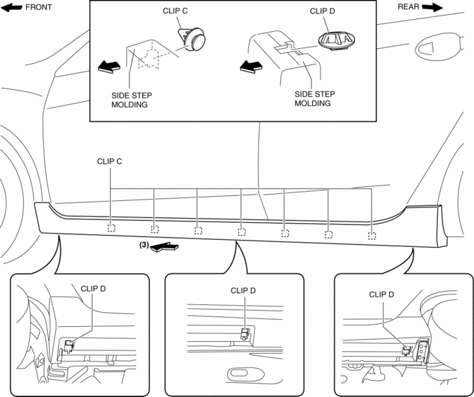
4. After removing the side step molding, remove clips C and D from the body using a fastener remover.
 Side Step Molding Installation
NOTE:
Double-sided adhesive tape has already been adhered to a new side step molding
for installation.
When a side step molding is to be reused, perform the following procedure:
1 ...
 Splash Shield Removal/Installation
Front Splash Shield
1. Remove the bolts and fastener then remove the front splash shield.
2. Install in the reverse order of removal.
Rear Splash Shield
1. Remove the fastener, screws and ca ...
Other materials:
Climate Control Unit Disassembly/Assembly [Manual Air Conditioner]
1. Disassemble in the order indicated in the figure.
1
Dial
2
Airflow mode wire
(See Wire Removal Note.)
(See Wire Installation Note.)
3
Air mix wire
(See Wire Removal Note.)
(See Wire Installation Note ...
Laser Sensor (Front)
The Smart City Brake Support (SCBS) laser sensor is installed at the top of
the windshield
near the rearview mirror.
Always keep the surface of the windshield around the laser sensor clean to
assure proper
operation of the Smart City Brake Support (SCBS) system.
WARNING
As ther ...
Wheel Hub, Steering Knuckle Removal/Installation
CAUTION:
Performing the following procedures without first removing the ABS wheel-speed
sensor may possibly cause an open circuit in the wiring harness if it is pulled
by mistake. Before performing the following procedures, disconnect the ABS wheel-speed
sensor connector (axle side) ...
