
Mazda 3 Service Manual: Steering Gear And Linkage Disassembly
CAUTION:
-
To prevent damage to the steering gear, secure it to the vise using a copper plate or clean cloth.
1. Disassemble in the order indicated in the table.
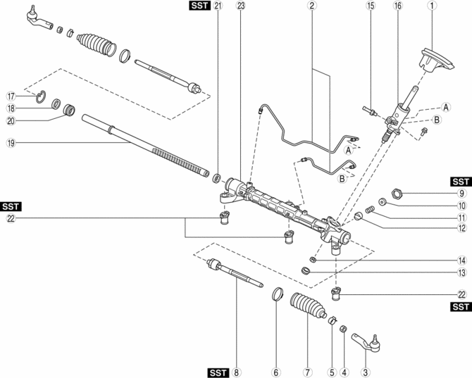
|
1 |
Floor seal |
|
2 |
Oil pipe |
|
3 |
Tie-rod end (See Tie-rod End Disassembly Note.) |
|
4 |
Locknut |
|
5 |
Boot clamp |
|
6 |
Boot band (See Boot Band Disassembly Note.) |
|
7 |
Boot |
|
8 |
Tie rod (See Tie Rod Disassembly Note.) |
|
9 |
Locknut (on adjusting cover) (See Locknut (on Adjusting Cover), Adjusting Cover Disassembly Note.) |
|
10 |
Adjusting cover (See Locknut (on Adjusting Cover), Adjusting Cover Disassembly Note.) |
|
11 |
Yoke spring |
|
12 |
Support yoke |
|
13 |
Housing cover |
|
14 |
Locknut (on pinion shaft) |
|
15 |
Return pipe |
|
16 |
Pinion shaft and valve housing component |
|
17 |
Clip |
|
18 |
Stopper |
|
19 |
Steering rack |
|
20 |
Rack bushing |
|
21 |
Oil seal (See Oil Seal Disassembly Note.) |
|
22 |
Mounting rubber (See Mounting Rubber Disassembly Note.) |
|
23 |
Gear housing |
Tie-rod End Disassembly Note
1. Place alignment marks as shown in the figure for proper installation.
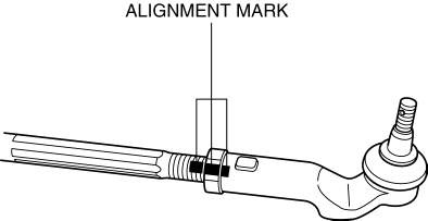
2. Remove the tie-rod end.
Boot Band Disassembly Note
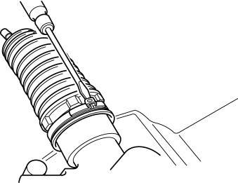
1. Insert a flathead screw driver into the boot band as shown in the figure, then press the caulked area outward to remove the boot band.
Tie Rod Disassembly Note
CAUTION:
-
If the steering rack is secured to a vise without using a cloth, the sliding surface of the steering rack could be damaged. Always use a clean cloth when securing the steering rack to the vise.
-
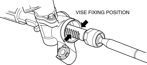
If the steering rack is secured to a vise in the incorrect position, the steering gear could fall off the vise and be damaged during the operation. Always secure the steering rack to the vise in the proper position.
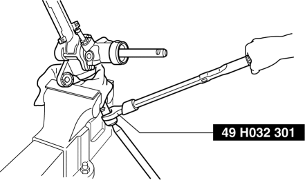
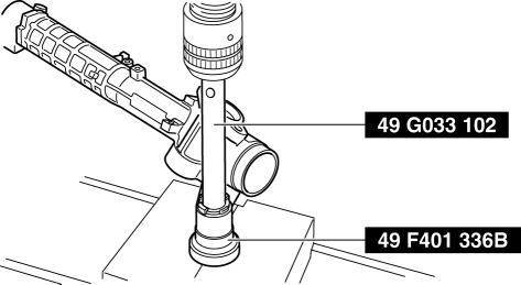
1. Protect the steering rack tooth surface using a clean cloth and secure it using a vise.
2. Remove the tie rod using the SST
.
Locknut (on Adjusting Cover), Adjusting Cover Disassembly Note
1. Remove the locknut using the SST
.
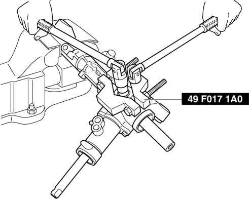
2. Remove the adjusting cover.
Oil Seal Disassembly Note
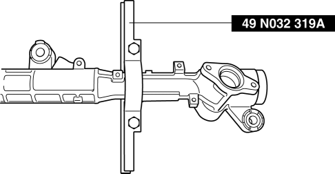
1. Install the SST
(49 N032 319A) to the gear housing as shown in the figure.
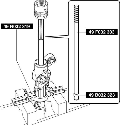
2. Insert the SSTs
(49 F032 303, 49 B032 323) into the valve housing side.
3. Remove the oil seal using the SSTs
and a press.
Mounting Rubber Disassembly Note
1. Remove the mounting rubber from the gear housing using the SSTs
and a press.
 Steering Gear And Linkage Assembly
CAUTION:
To prevent damage to the steering gear, secure it to the vise using a copper
plate or clean cloth.
1. Assemble in the order indicated in the table.
1
...
 Steering Gear And Linkage Inspection
Steering Rack Inspection
1. Inspect for cracking, damage, and tooth wear.
If there is any malfunction, replace the steering rack.
2. Measure the steering rack warp.
If it ex ...
Other materials:
Steering SST
49 H032 301
Wrench
49 F017 1A0
Universal wrench
49 F032 303
Handle
49 B032 323
Rod seal remover body
49 N032 319A
Support plate
49 ...
Oil Seal (Differential) Replacement [A26 M R]
1. On level ground, jack up the vehicle and support it evenly on safety stands.
2. Drain the oil from the transaxle..
3. Remove the front tires..
4. Remove the splash shield..
5. Remove the aerodynamic under cover No.2..
6. Separate the drive shaft and joint shaft from the transaxle..
7 ...
Front Fog Light Relay Removal/Installation
1. Disconnect the negative battery cable..
2. Remove the front mudguard.(RH).
3. Remove the front fog light relay case.
4. Remove the cover.
5. Remove the front fog light relay.
6. Install in the reverse order of removal..
Front Fog Light Relay Installation Note
1. Install the front ...
