Mazda 3 Service Manual: Steering Gear And Linkage Inspection
Steering Rack Inspection
1. Inspect for cracking, damage, and tooth wear.
-
If there is any malfunction, replace the steering rack.
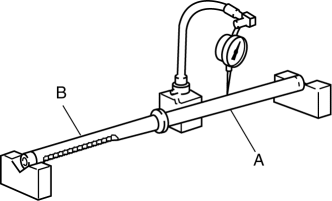
2. Measure the steering rack warp.
-
If it exceeds the maximum specification, replace the steering rack.
-
Steering rack runout
-
Large diameter portion (near point A): 0.15 mm {0.006 in} max.
-
Small diameter portion (near point B): 0.20 mm {0.008 in} max.
Tie-rod End Inspection
1. Inspect the tie-rod end for damage and the boot for cracks.
-
If there is any malfunction, replace the tie-rod end.
2. Inspect for excessive play.
-
If there is any malfunction, replace the tie-rod end.
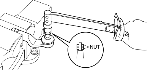
3. Rotate the ball joint 5 times
.
4. Install two nuts to the ball joint and measure the tie-rod end rotational torque using a torque wrench.
-
If not within the specification, replace the tie-rod end.
-
Tie-rod end rotational torque
-
0.5—3.0 N·m {5.1—30 kgf·cm, 4.5—26 in·lbf}
Tie rod Inspection
1. Inspect for bending and damage.
-
If there is any malfunction, replace the tie rod.
2. Inspect for excessive play.
-
If there is any malfunction, replace the tie rod.
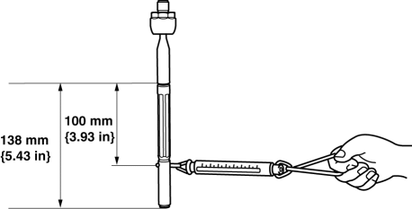
3. Swing the ball joint 10 times
.
4. Measure the ball joint swing torque using a pull scale.
-
If it exceeds the specification, replace the tie rod.
-
Tie rod swing torque
-
0.4—4.0 N·m {4.1—40 kgf·cm, 3.6—35 in·lbf}
-
[Pull scale reading 0.6—29.3 N {0.06—2.98 kgf, 0.14—6.58 lbf}]
 Steering Gear And Linkage Disassembly
CAUTION:
To prevent damage to the steering gear, secure it to the vise using a copper
plate or clean cloth.
1. Disassemble in the order indicated in the table.
1
...
 Steering Gear And Linkage Removal/Installation
CAUTION:
Performing the following procedures without first removing the ABS wheel-speed
sensor may possibly cause an open circuit in the wiring harness if it is pulled
by mistake. Before ...
Other materials:
Power sources that can be used
To properly charge the Subaru Solterra, it is essential to use an
external power source that fully meets the specified electrical requirements. Always
verify that the selected power source complies with these conditions before initiating
the charging process to ensure safe and efficient operat ...
Vehicle Speed Sensor (VSS) Inspection [FS5 A EL]
On-Vehicle Inspection
1. Inspect the power supply circuit for the VSS.
a. Remove the insulator from the transaxle.
b. Disconnect the VSS connector.
c. Switch the ignition to ON (engine off).
d. Measure the voltage at VSS connector terminal A (harness-side).
If there is a ...
Air Cleaner Element Inspection [Mzr 2.0, Mzr 2.5]
1. Remove the air cleaner element..
2. Inspect the following items:
Has the replacement interval come?
Is the air cleaner element soiled, damaged, or bent?
Are the air cleaner case and the air cleaner element correctly sealed?
Is the correct air cleaner element inst ...
