Mazda 3 Service Manual: Steering Wheel And Column Inspection
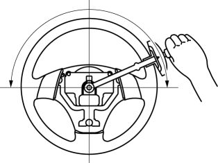
Play Inspection
1. With the wheels in the straight-ahead position, start the engine.
2. Turn the steering wheel to the left and right gently, then verify that the steering wheel play is within the specification.
-
Steering wheel play
-
0—30 mm {0—1.18 in} (When hydraulic operating)
Looseness, Excessive Play Inspection
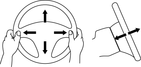
1. Inspect the steering wheel for looseness or excessive play in the axial direction of the shaft and four locations around the steering wheel.

-
If there is any malfunction, inspect the following, and repair or replace the applicable part.
-
Column bearing wear
-
Looseness of the steering wheel installation part
-
Looseness of the column installation area
-
Excessive play of the steering shaft joint
-
Excessive play of the steering gear
Steering Force Inspection
1. Verify that the equipped tire size and tire air pressure is as specified.
2. With the vehicle on a hard, level surface, put the wheels in the straight-ahead position.
WARNING:
-
Handling the air bag module improperly can accidentally operate (deploy) the air bag module, which may seriously injure you. Read the service warnings before handling the air bag module..
3. Remove the air bag module..
4. Start the engine and idle it.
5. Verify that the EHPAS warning light does not illuminate.
6. Inspect the steering force using a torque wrench.

-
If not within the specification, verify the following:
-
No air in steering system
-
No fluid leakage at hose or connectors
-
Function of oil pump and steering gear
-
Steering wheel force (reference value)
-
7.8 N·m {80 kgf·cm, 69 in·lbf} or less
NOTE:
-
Comparing another vehicle of the same model under the same conditions is an acceptable inspection method.
-
The steering force varies with conditions indicated below.
-
Road conditions: Such as dry, wet, asphalt, or concrete
-
Tire condition: such as brand, wear, and tire pressure
 Steering Shaft Inspection
1. Inspect the column bearing for excessive play and damage.
2. Verify that the measurement of the steering shaft indicated in the figure
is as specified.
If not within the specificati ...
 Steering Wheel And Column Removal/Installation [With Advanced Keyless Entry
And Push Button Start System]
WARNING:
Handling the air bag module improperly can accidentally operate (deploy)
the air bag module, which may seriously injure you. Read the service warnings
before handling the air ba ...
Other materials:
Climate Control Unit Inspection [Full Auto Air Conditioner]
1. Remove the climate control unit with the connector connected..
2. Switch the ignition to ON.
3. Connect the negative (-) lead of the tester to body ground.
4. By inserting the positive (+) lead of the tester into each climate control
unit terminal, measure the voltage according to the ter ...
Entertainment System
Outline
Auxiliary jack/USB port has been adopted.
USB adapter has been adopted.
An audio unit which supports USB devices such as USB memory or iPods has
been adopted.
911 assist function has been added to the Bluetooth unit.
RDS-TMC (Radio Data System-Traffi ...
Aluminum Wheel Maintenance
A protective coating is provided over the
aluminum wheels. Special care is needed
to protect this coating.
CAUTION
Do not use any detergent other than
mild detergent. Before using any
detergent, verify the ingredients.
Otherwise, the product could discolor
or stain the alumi ...
