Mazda 3 Service Manual: Vehicle Speed Sensor (VSS) Inspection [FS5 A EL]
On-Vehicle Inspection
1. Inspect the power supply circuit for the VSS.
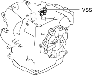
a. Remove the insulator from the transaxle.
b. Disconnect the VSS connector.
c. Switch the ignition to ON (engine off).
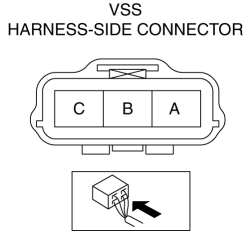
d. Measure the voltage at VSS connector terminal A (harness-side).
-
If there is any malfunction, repair wiring harness between VSS and AT main relay.
-
VSS specification
-
B+
e. Switch the ignition to off.
f. Connect the VSS connector.
2. Inspect the GND circuit for the VSS.
a. Switch the ignition to off.
b. Measure the voltage at VSS connector terminal C (harness-side).
-
If there is any malfunction, repair wiring harness between VSS and GND.
-
VSS specification
-
Below 1.0 V
3. Inspect the signal circuit for the VSS.
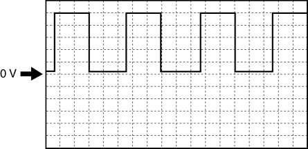
a. Connect the oscilloscope to the following TCM connector terminals and set it as below.
-
(+) lead: TCM terminal Z
-
(-) lead: battery negative terminal
-
Oscilloscope setting: 1 V/DIV (Y), 2 ms/DIV (X), DC range
b. Start the engine.
c. Measure the wave form when the following conditions are met.
-
Gear position: 3GR
-
Vehicle speed: 30 km/h {19 mph}
-
If there is any malfunction, replace the VSS..
 Passenger Compartment Temperature Sensor Removal/Installation [Full Auto Air
Conditioner]
Passenger Compartment Temperature Sensor Removal/Installation [Full Auto Air
Conditioner]
1. Disconnect the negative battery cable..
2. Remove the following parts:
a. Front scuff plate.
b. Front side trim.
c. Dashboard under cover.
d. Upper panel.
e. Shift lever knob (MTX).
f ...
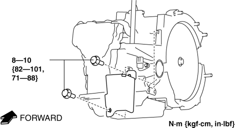
 Vehicle Speed Sensor (VSS) Removal/Installation [FS5 A EL]
CAUTION:
If foreign materials are stuck to the sensor, disturbance by magnetic flux
can cause sensor output to be abnormal and thereby negatively affect control.
Make sure that foreign m ...
Other materials:
Rain Sensor Removal/Installation
1. Disconnect the negative battery cable..
2. Spread open the rain sensor cover in the direction of the arrows and disengage
tabs A to remove it.
3. Disconnect the rain sensor connector.
4. Slide rain sensor tab B in the direction of the arrow shown in the figure
and detach tab B. ...
No.16 Judder Upon Torque Converter Clutch (TCC) Operation [FS5 A EL]
16
Judder upon torque converter clutch (TCC) operation
DESCRIPTION
Vehicle jolts when TCC is engaged.
POSSIBLE CAUSE
Poor TCC engagement due to either slippage because the TCC is stuck
...
Front Oil Seal Replacement [Mzr 2.0, Mzr 2.5]
1. Remove the battery cover..
2. Disconnect the negative battery cable..
3. Remove the plug hole plate..
4. Disconnect the wiring harness.
5. Remove the ignition coils..
6. Remove the spark plugs..
7. Remove the ventilation hose.
8. Remove the oil level gauge.
9. Remove the cylinder ...
