Mazda 3 Service Manual: Blind Spot Monitoring (Bsm) Control Module Removal/Installation
CAUTION:
-
If the BSM control modules are installed with the left and right modules reversed, a DTC will be displayed and system will enter the fail-safe function. Therefore, confirm that the left/right BSM control modules are installed correctly.
1. Disconnect the negative battery cable..
2. Remove the rear combination light..
3. Remove the rear bumper..
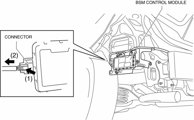
4. Pull the connector in the direction shown by the arrow (2) in the figure and remove it while pressing the tab in the direction shown by arrow (1).

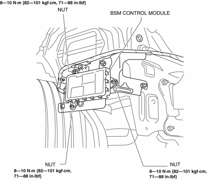
5. Remove the nuts.

6. Remove the BSM control module.
7. Install in the reverse order of removal.
8. Perform the blind spot monitoring radar test..
 Blind Spot Monitoring (Bsm) Control Module Inspection
1. Disconnect the negative battery cable.
2. Remove the rear combination light..
3. Remove the rear bumper..
4. Connect the negative battery cable..
5. Measure the voltage at each terminal is ...
 Blind Spot Monitoring (Bsm) Indicator Light Inspection
NOTE:
The BSM indicator light is integrated with the outer mirror glass.
1. Inspect the the outer mirror glass.. ...
Other materials:
Drive Selection
Drive selection is a system to switch the vehicle's drive mode. When the
sport mode
is selected, vehicle's response against accelerator operation is enhanced. This
provides
additional quick acceleration which may be needed to safely make maneuvers such
as lane
changes, merging onto freeways ...
Dashboard Precautions
Prevent caustic solutions such as perfume
and cosmetic oils from contacting the
dashboard. They will damage and discolor
the dashboard. If these solutions get on the
dashboard, wipe them off immediately.
CAUTION
Do not use glazing agents.
Glazing agents contain ingredients
which ...
Foot Brake
This vehicle has power-assisted brakes
that adjust automatically through normal
use.
Should power-assist fail, you can stop by
applying greater force than normal to the
brake pedal. But the distance required to
stop will be greater than usual.
WARNING
Do not coast with the engine ...
