Mazda 3 Owners Manual: i-ELOOP
On conventional vehicles, the kinetic energy that is generated when the vehicle is decelerated by applying the brakes or during engine braking ends up being discarded as heat. By utilizing this discarded kinetic energy to generate electricity and use it to power the vehicle's electrical devices and accessories such as the A/C and audio, fuel consumption can be reduced. Mazda's system for generating electricity from this kinetic energy is called the Regenerative Braking System (i-ELOOP).
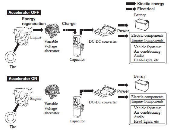
A capacitor is incorporated as the device for storing the generated electricity, which can store and use large amounts of electricity instantly.
CAUTION
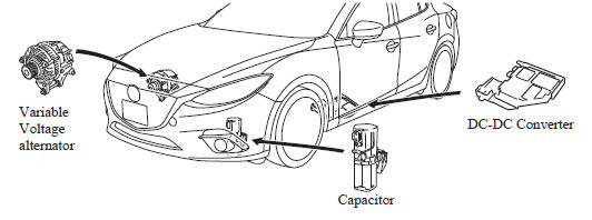
High-current electricity fl ows through the following areas, therefore
do not touch them.
|
NOTE
- When installing high power consumption devices such high-output speakers, consult an Authorized Mazda Dealer.
- A difference in the fuel economy may occur depending on use conditions such as with the A/C and headlights.
- If the capacitor is to be disposed of, always consult an Authorized Mazda Dealer. For details, go to the following URL.
i-ELOOP Indicator Light/Control Status Display
The driver is notified of the i-ELOOP power generating status and the vehicle conditions by the i-ELOOP indicator light and the control status display.
i-ELOOP Indicator Light

Illuminated (vehicle without type B audio)
The light turns on during power generation.
Flashing
If the engine is started after the vehicle has not been driven for a long period of time, the i-ELOOP indicator light may flash.
Leave the engine idling and wait until the indicator light turns off.
NOTE
- The beep will sound if the vehicle is
driven while the i-ELOOP indicator
light is flashing. In addition, if you
turn the steering wheel while the light
is flashing, it will feel heavier than
normal, but this does not indicate an
abnormality. Stop the vehicle in a safe
location with the engine running and do
not attempt to turn the steering wheel.
The steering operation will return to normal after the i-ELOOP indicator light stops flashing.
- (Vehicles with type B audio)
A notification is displayed in the center
display and the i-ELOOP indicator light
flashes at the same time.
Refer to Warning Message Indicated on Display on .
Control status display (vehicles with type B audio)
The i-ELOOP power generating status is displayed in the center display.
Refer to Control Status Display on .
 Dynamic Stability Control
(DSC)
Dynamic Stability Control
(DSC)
The Dynamic Stability Control (DSC)
automatically controls braking and engine
torque in conjunction with systems such
as ABS and TCS to help control side slip
when driving on slippery surfaces, or ...
 Fuel Economy Monitor
For vehicles with type B audio, the Control Status and Fuel Consumption are
switched and
displayed by operating each icon in the display.
In addition, after completing a trip, the total energy e ...
Other materials:
Transaxle Oil Inspection [G35 M R]
1. Park the vehicle on level ground.
2. Remove the aerodynamic under cover No.2..
3. Remove the oil level plug and washer.
4. Verify that the oil is near the brim of the plug port.
If the oil level is lower than the low level, add the specified amount and
type of oil through the ...
Drive Belt Auto Tensioner Inspection [Mzr 2.0, Mzr 2.5]
MZR 2.0
1. Remove the generator drive belt with the A/C drive belt still installed and
set it out of the way..
2. Verify that the drive belt auto tensioner moves smoothly in the operational
direction.
If it does not move smoothly, replace the drive belt auto tensioner..
3. T ...
Cooling System Service Warnings [Mzr 2.0, Mzr 2.5]
WARNING:
Never remove the cooling system cap or loosen the radiator drain plug while
the engine is running, or when the engine and radiator are hot. Scalding engine
coolant and steam may shoot out and cause serious injury. It may also damage
the engine and cooling system.
Tu ...
