Mazda 3 Service Manual: Joint Shaft Disassembly [Mzr 2.3 Disi Turbo]
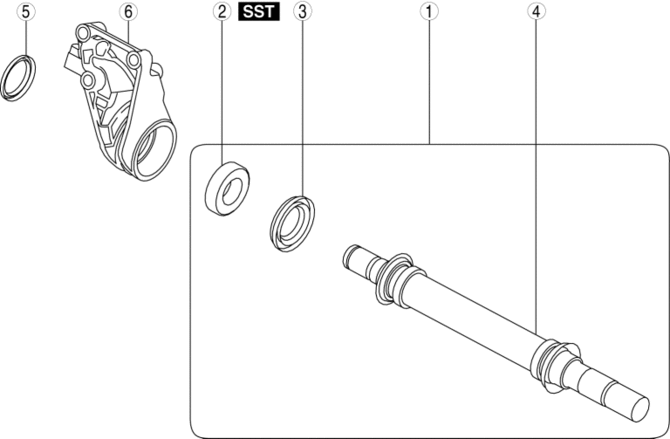
1. Disassemble in the order indicated in the table.
|
1 |
Joint shaft component . |
|
2 |
Bearing . |
|
3 |
Dust seal (LH) |
|
4 |
Joint shaft |
|
5 |
Dust seal (RH) |
|
6 |
Bracket |
Joint Shaft Component Disassembly Note
1. Secure the bracket to the vise at the position shown in the figure and remove the joint shaft component using the plastic hammer.
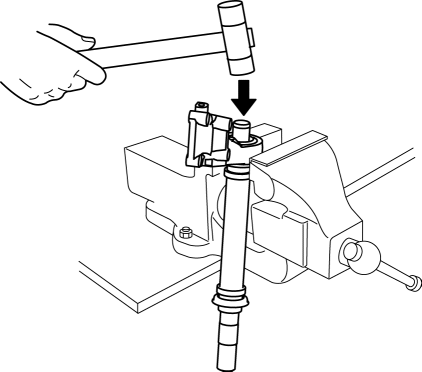
CAUTION:
-
Do not drop the joint shaft because it could be damaged.
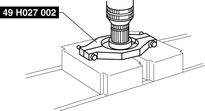
Bearing Disassembly Note
1. Set the SST
and joint shaft to the press.
 Joint Shaft Disassembly [Mzr 2.0, Mzr 2.5]
1. Disassemble in the order indicated in the table.
1
Joint shaft component
.
2
Bearing
.
3
Dust seal (LH)
...
 Joint Shaft Disassembly [Skyactiv G 2.0]
1. Disassemble in the order indicated in the table.
1
Snap ring
2
Joint shaft component
.
3
Dust seal
...
Other materials:
Applicable Bluetooth ® specification
(Recommended)
Ver. 1.1/1.2/2.0 EDR/2.1 EDR/3.0
(conformity)
Response profile
A2DP (Advanced Audio Distribution
Profile) Ver. 1.0/1.2
AVRCP (Audio/Video Remote Control
Profile) Ver. 1.0/1.3/1.4
A2DP is a profile which transmits only
audio to the Bluetooth ® unit. If your
Bluetooth ® audio device ...
Cargo and luggage
When using the Subaru Solterra, carefully follow these guidelines
regarding cargo handling, storage safety, and load capacity to maintain optimal
vehicle performance and passenger protection.
Proper loading in the Subaru Solterra not only improves driving stability
but also helps prevent unne ...
Clock Spring Removal/Installation
1. Disconnect the negative battery cable..
2. Remove the driver-side air bag module..
3. Remove the steering wheel..
4. Remove the column cover.
5. Remove the connectors.
6. Remove the tab direction of the arrow shown in the figure.
7. Remove the screws.
8. Remove the clock spring. ...
