
Mazda 3 Service Manual: Wheel Alignment Pre Inspection
1. Park the vehicle on a level ground, in an unloaded condition*, and with the wheels straight forward.
*: Unloaded condition.....Fuel tank is full. Engine coolant and engine oil are at specified level. Spare tire, jack and tools are in designated position.
2. Inspect the tire pressure.
-
Adjust to the recommended pressure if necessary..
3. Inspect the wheel bearing play.
-
Correct if necessary..
4. Inspect the wheel runout.
-
Correct if necessary..
5. Rock the vehicle, and verify that there is no looseness in the steering wheel joint and suspension ball joint.
6. Rock the vehicle, and verify that the shock absorber operates properly.
7. Measure height H from the center of the wheel to the fender brim.
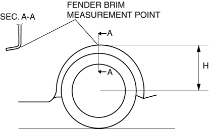
8. Verify that the difference between the left and right dimension H is within the specification.
-
If it exceeds the specification, repeat the Step 2—7.
-
Standard
-
10 mm {0.39 in} or less
 Tire House Trim Removal/Installation
4SD
1. Remove the rear seat cushion..
2. Remove the rear scuff plate..
3. Partially peel back the seaming welt.
4. Remove the fastener.
5. Pull the tire house trim in the direction of arrow s ...
 Wheel Balance Adjustment
CAUTION:
Adjust the outer wheel balance first, then the inner wheel balance.
Be careful not to scratch the wheels.
Adhesive-type Balance Weight (Outer)
1. Remove the old balance ...
Other materials:
Automatic Transaxle Removal/Installation [Fw6 A EL]
CAUTION:
Secure the steering wheel using tape or a cable to prevent the steering shaft
from rotating after disconnecting the steering shaft. If the steering wheel
rotates after the steering shaft and the steering gear and linkage are disconnected,
the internal parts of the clock spr ...
Seat Operation
*1: With power operation seat only
1. Seat Slide
(Manual Seat)
To move a seat forward or backward, raise the lever and slide the seat to the
desired position
and release the lever.
Make sure the lever returns to its original position and the seat is locked in
place by
attempting to p ...
Parking Support Brake function (static objects front and rear of the vehicle/static
objects around the vehicle)
Within the Subaru Solterra, the Parking Support Brake system continuously
monitors the driving path for stationary obstacles such as walls or fixed structures.
If the sensors detect a static object and the system determines that a collision
could occur — for example due to unintended acceler ...
