
Mazda 3 Service Manual: Auxiliary Jack Inspection
1. Disconnect the negative battery cable..
2. Remove the following parts:
a. Upper panel.
b. Shift lever knob (MTX).
c. Selector lever knob (ATX).
d. Shift panel.
e. Side wall.
f. Console.
g. Auxiliary jack.
3. Connect a commercially-available nonresistant plug to the auxiliary jack.
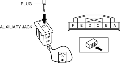
4. Verify that the continuity between the auxiliary jack terminals is as indicated in the table.
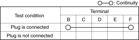
-
If not as indicated in the table, replace the auxiliary jack.
 Audio Unit Removal/Installation
Without Display
CAUTION:
When installing the audio unit, make sure that the wiring harness and antenna
feeder are not caught between the unit and dashboard. If the wiring harness
or the ...
 Auxiliary Jack Removal/Installation
1. Disconnect the negative battery cable..
2. Remove the following parts:
a. Upper panel.
b. Shift lever knob (MTX).
c. Selector lever knob (ATX).
d. Shift panel.
e. Side wall.
f. Consol ...
Other materials:
Front Stabilizer Control Link Inspection
1. Remove the front stabilizer control link from the vehicle.. (See FRONT STABILIZER
REMOVAL/INSTALLATION [MZR 2.3 DISI Turbo]
2. Inspect for bending or damage. If there is any malfunction, replace the stabilizer
control link.
3. Rotate the ball joint stud 10 times and shake it side to side ...
Drive Shaft (Tripod Joint) Disassembly/Assembly
1. Disassemble in the order indicated in the table.
2. Assemble in the reverse order of disassembly.
1
Boot band (transaxle side)
(See Boot Band (Transaxle Side) Disassembly Note.)
(See Boot Band (Transaxle Side) Assembly Note.)
2
Cli ...
Front Seat Belt Removal/Installation [Standard Deployment Control System]
WARNING:
Handling the front seat belt (pre-tensioner seat belt) improperly can accidentally
deploy the pre-tensioner seat belt, which may seriously injure you. Read the
air bag system service warnings and cautions before handling the front seat
belt..
WARNING:
The side ...
