
Mazda 3 Service Manual: Check Valve (One Way) Inspection [Mzr 2.3 Disi Turbo]
1. Disconnect the vacuum hose connected between the check valve and the purge solenoid valve from the purge solenoid valve..
2. Disconnect the vacuum hose connected between the check valve (one-way) and the intake manifold from the intake manifold..
3. Blow through the check valve (one-way) and verify that air flows as specified.
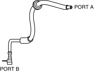
Specification
|
Condition |
Airflow |
|
Air applied from port A to B |
Yes |
|
Air applied from port B to A |
No* |
* The check valve (one-way) is normal if the aeration to port A is 3.5 kPa/min {0.03 kgf/cm2 min, 0.5 psi/min} or less
when 130 kPa {1.32 kgf/cm2, 18.9 psi}
is applied to port B.
-
If not as specified, replace the check valve (one-way)..
 Charcoal Canister Removal/Installation [Mzr 2.0, Mzr 2.5]
Except for Mexico
1. Remove in the order indicated in the table.
1
Evaporative hose
2
Quick release connector
(See QUICK RELEASE CONNECTOR ...
 Check Valve (Two Way) Removal/Installation [Mzr 2.0, Mzr 2.5]
Mexico
NOTE:
The check valve (two-way) cannot be removed as it is built into the rollover
valve.
The rollover valve cannot be removed as it is built into the fuel tank.
1. Re ...
Other materials:
Auto Lock/Unlock Function
WARNING
Do not pull the inner handle on a front
door:
Pulling the inner handle on a front
door while the vehicle is moving
is dangerous. Passengers can fall
out of the vehicle if the door opens
accidentally , which could result in
death or serious injury.
When ...
Moonroof
The moonroof can be opened or closed
electrically only when the ignition is
switched ON.
WARNING
Do not let passengers stand up or
extend part of the body through the
open moonroof while the vehicle is
moving:
Extending the head, arms, or other
parts of the body throu ...
Down Switch Inspection [FS5 A EL]
1. Perform the following procedures.
a. Remove the battery cover..
b. Disconnect the negative battery cable.
c. Remove the console..
d. Disconnect the selector lever component connector.
2. Inspect the continuity between the selector lever component terminals C and
H.
If ...
