Mazda 3 Service Manual: Clock Switch Inspection
NOTE:
-
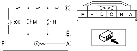
Clock switch built with the hazard warning switch.
1. Disconnect the negative battery cable..
2. Remove the clock switch..
3. Verify resistance between the clock switch terminals.
-
If the resistance is not as specified, replace the clock switch.
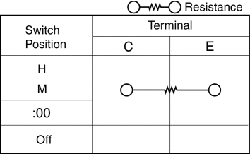
Between the terminal C—E resistance
|
Switch position |
Resistance (ohm) |
|
H |
48.45—53.55 |
|
M |
86.45—95.55 |
|
:00 |
142.5—157.5 |
4. Connect the positive battery to the clock switch terminal A, the negative battery to the clock switch terminal F.
5. Verify the LED illuminates.
-
If there is any malfunction, replace the clock switch.
 Clock Spring Removal/Installation
1. Disconnect the negative battery cable..
2. Remove the driver-side air bag module..
3. Remove the steering wheel..
4. Remove the column cover.
5. Remove the connectors.
6. Remove the t ...
 Information Display Input/Output Check Mode
NOTE:
In this mode, it is possible to verify the items in the following chart.
Check Code Table
Check code
Check item
Related items
...
Other materials:
Rain Sensor Removal/Installation
1. Disconnect the negative battery cable..
2. Spread open the rain sensor cover in the direction of the arrows and disengage
tabs A to remove it.
3. Disconnect the rain sensor connector.
4. Slide rain sensor tab B in the direction of the arrow shown in the figure
and detach tab B. ...
Camshaft Position (CMP) Sensor Inspection [Mzr 2.0, Mzr 2.5]
Visual Inspection
CAUTION:
When replacing the CMP sensor, make sure there is no foreign material on
it such as metal shavings. If it is installed with foreign material, the sensor
output signal will malfunction resulting from fluctuation in magnetic flux and
cause a deterioration i ...
Radiator Removal/Installation [Mzr 2.0, Mzr 2.5]
WARNING:
Never remove the cooling system cap or loosen the radiator drain plug while
the engine is running, or when the engine and radiator are hot. Scalding engine
coolant and steam may shoot out and cause serious injury. It may also damage
the engine and cooling system.
Tu ...
