Mazda 3 Service Manual: Crankshaft Position (CKP) Sensor Removal/Installation [Mzr 2.0, Mzr 2.5]
Removal
CAUTION:
-
When foreign material such as an iron chip is on the CKP sensor, it can cause abnormal output from the sensor because of flux turbulence and adversely affect the engine control. Be sure there is no foreign material on the CKP sensor when replacing.
-
Do not assemble the CKP sensor or change the installation position using any method other than the following. Otherwise, it could negatively affect engine controls, such as the ignition timing and fuel injection.
1. Remove the battery cover..
2. Disconnect the negative battery cable..
3. Perform the following procedure for easier access.
a. Remove the aerodynamic under cover No.2..
b. Remove the front splash shield (RH)..
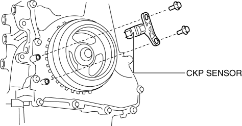
4. Disconnect the CKP sensor connector.
5. Remove the CKP sensor.
Installation
CAUTION:
-
When foreign material such as an iron chip is on the CKP sensor, it can cause abnormal output from the sensor because of flux turbulence and adversely affect the engine control. Be sure there is no foreign material on the CKP sensor when replacing.
-
Do not assemble the CKP sensor or change the installation position using any method other than the following. Otherwise, it could negatively affect engine controls, such as the ignition timing and fuel injection.
1. Perform the following procedure so that cylinder No.1 is at TDC.
a. Remove the wheel and tire (front right side).
b. Disconnect the drive shaft (RH) from joint shaft, set the drive shaft (RH) out of the way. (MTX).
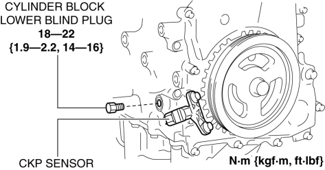
c. Remove the cylinder block lower blind plug and install the SST
.
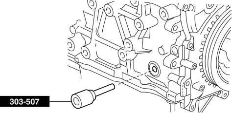
d. Rotate the crankshaft pulley clockwise until the crank weight contacts the SST
so that cylinder No.1 is at TDC.
2. Fit the center of the CKP sensor with the fifth tooth (counting counterclockwise from the empty space A as shown in the figure) of the pulse wheel.
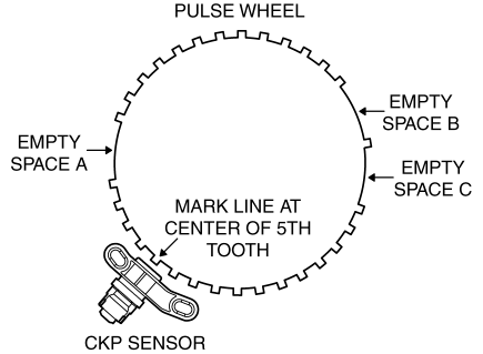
CAUTION:
-
If the line is not accurately drawn, ignition timing, fuel injection and other engine control systems will be adversely effected. Draw the straight line carefully using a straight edge.
3. Align the center line of the CKP sensor and the line drawn in Step 2, then install the sensor.
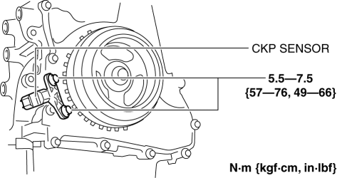
4. Install the CKP sensor fitting bolts.
5. Remove the SST
then install the cylinder block lower blind plug.
6. Install the drive shaft (RH). (MTX).
7. Install the wheel and tire (front right side).
 Crankshaft Position (CKP) Sensor Inspection [Mzr 2.0, Mzr 2.5]
Visual Inspection
CAUTION:
When foreign material such as an iron chip is on the CKP sensor, it can cause
abnormal output from the sensor because of flux turbulence and adversely affect
...

Other materials:
Keyless Entry System
This system uses the key buttons to
remotely lock and unlock the doors and
the liftgate/trunk lid, and opens the trunk
lid.
The system can start the engine without
having to take the key out of your purse or
pocket.
It can also help you signal for attention.
Operating the theft-deterre ...
Charcoal Canister Inspection [Mzr 2.0, Mzr 2.5]
Leakage Inspection
1. Perform the following procedures:
Assemble the hose used for inspection to port A.
Cover ports B and C with the caps.
Except for Mexico
Mexico
CAUTION:
Do not apply a pressure 20 kPa {150 mmHg, 5.91 inHg} or more to the charcoal
cani ...
Emergency flashers
The emergency flashers in the Subaru Solterra are designed to alert
surrounding drivers when the vehicle must be stopped unexpectedly due to a breakdown,
hazard, or other urgent situation.
Operating instructions
Press the emergency flasher switch located in the Subaru Solterra cabin.
All turn ...
