Mazda 3 Owners Manual: i-ELOOP
On conventional vehicles, the kinetic energy that is generated when the vehicle is decelerated by applying the brakes or during engine braking ends up being discarded as heat. By utilizing this discarded kinetic energy to generate electricity and use it to power the vehicle's electrical devices and accessories such as the A/C and audio, fuel consumption can be reduced. Mazda's system for generating electricity from this kinetic energy is called the Regenerative Braking System (i-ELOOP).
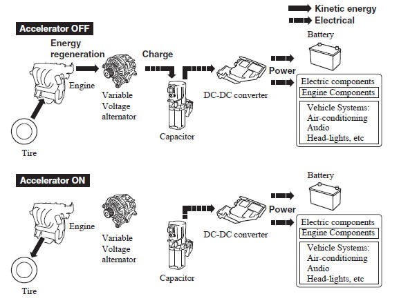
A capacitor is incorporated as the device for storing the generated electricity, which can store and use large amounts of electricity instantly.
CAUTION
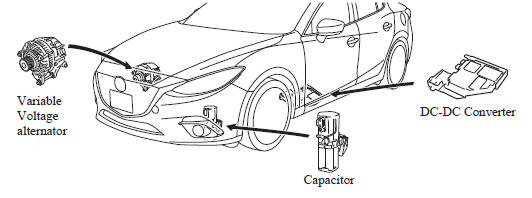
High-current electricity fl ows through the following areas, therefore
do not touch them.
|
NOTE
- When installing high power consumption devices such high-output speakers, consult an Authorized Mazda Dealer.
- A difference in the fuel economy may occur depending on use conditions such as with the A/C and headlights.
- If the capacitor is to be disposed of, always consult an Authorized Mazda Dealer. For details, go to the following URL.
i-ELOOP Indicator Light/Control Status Display
The driver is notified of the i-ELOOP power generating status and the vehicle conditions by the i-ELOOP indicator light and the control status display.
i-ELOOP Indicator Light

Illuminated (vehicle without type B audio)
The light turns on during power generation.
Flashing
If the engine is started after the vehicle has not been driven for a long period of time, the i-ELOOP indicator light may flash.
Leave the engine idling and wait until the indicator light turns off.
NOTE
- The beep will sound if the vehicle is
driven while the i-ELOOP indicator
light is flashing. In addition, if you
turn the steering wheel while the light
is flashing, it will feel heavier than
normal, but this does not indicate an
abnormality. Stop the vehicle in a safe
location with the engine running and do
not attempt to turn the steering wheel.
The steering operation will return to normal after the i-ELOOP indicator light stops flashing.
- (Vehicles with type B audio)
A notification is displayed in the center
display and the i-ELOOP indicator light
flashes at the same time.
Refer to Warning Message Indicated on Display on .
Control status display (vehicles with type B audio)
The i-ELOOP power generating status is displayed in the center display.
Refer to Control Status Display on .
 Dynamic Stability Control
(DSC)
Dynamic Stability Control
(DSC)
The Dynamic Stability Control (DSC)
automatically controls braking and engine
torque in conjunction with systems such
as ABS and TCS to help control side slip
when driving on slippery surfaces, or ...
 Fuel Economy Monitor
For vehicles with type B audio, the Control Status and Fuel Consumption are
switched and
displayed by operating each icon in the display.
In addition, after completing a trip, the total energy e ...
Other materials:
Rear Outer Handle Removal/Installation
1. Fully close the rear door glass.
2. Disconnect the negative battery cable..
3. Remove the rear door trim..
4. Remove the service hole cover.
5. Remove the screw from the service hole.
NOTE:
The screw cannot be removed because of the stopper.
6. Press the tab on the ...
Clutch Unit Removal/Installation [C66 M R]
1. Remove the battery cover..
2. Disconnect the negative battery cable..
3. Remove the aerodynamic under cover No.2 and the splash shield as a single
unit..
4. Drain the manual transaxle oil..
5. Disconnect and/or remove the following parts in the engine compartment.
a. Remove the batte ...
Tire Inflation Pressure
WARNING
Always infl ate the tires to the correct
pressure:
Overinfl ation or underinfl ation of tires
is dangerous. Adverse handling or
unexpected tire failure could result in a
serious accident.
Refer to Tires on .
Use only a Mazda-genuine tire valve
cap:
Use ...
