Mazda 3 Service Manual: On Board Diagnostic System Simulation Inspection [Fw6 A EL]
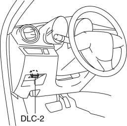
1. Connect the M-MDS (IDS) to the DLC-2.
2. After the vehicle is identified, select the following items from the initialization screen of the IDS.
a. Select “DataLogger”.
b. Select “Modules”.
c. Select “TCM”.
3. Select the simulation items from the PID table.
4. Perform the active command modes function, inspect the operations for each parts.
-
If the operation of output parts cannot be verified after the active command mode inspection is performed, this could indicate the possibility of an open or short circuit, sticking, or operation malfunction in the output parts.
|
Item |
Description |
Unit/Condition |
Operation condition |
|
SS_ON-OFF |
On/off solenoid condition |
Off/On |
Under the following conditions:
|
|
SS1_C |
Shift solenoid No.1 target current |
A |
Under the following conditions:
|
|
SS2_C |
Shift solenoid No.2 target current |
A |
Under the following conditions:
|
|
SS3_C |
Shift solenoid No.3 target current |
A |
Under the following conditions:
|
|
SS4_C |
Shift solenoid No.4 target current |
A |
Under the following conditions:
|
|
SSLU_C |
TCC control solenoid target current |
A |
Under the following conditions:
|
|
SSP_C |
Pressure control solenoid target current |
A |
Idling at P or N position |
 On Board Diagnostic System Simulation Inspection [FS5 A EL]
1. Connect the M-MDS(IDS) to the DLC-2.
2. After the vehicle is identified, select the following items from the initialization
screen of the IDS.
a. Select "DataLogger".
b. Selec ...
 PID/Data Monitor Inspection [Bcm]
1. Connect the M-MDS (IDS) to the DLC-2.
2. After the vehicle is identified, select the following items from the initialization
screen of the IDS.
a. Select “DataLogger”.
b. Select “ ...
Other materials:
Air Bag Module And Pre Tensioner Seat Belt Deployment Procedures [Two Step Deployment
Control System]
WARNING:
A live (undeployed) air bag module or pre-tensioner seat belt may accidentally
operate (deploy) when it is disposed of and cause serious injury. Do not dispose
of a live (undeployed) air bag module and pre-tensioner seat belt. If the SSTs
(Deployment tool and Adapter harn ...
Bluetooth® Audio (Type A)
Applicable Bluetooth ® specification
(Recommended)
Ver. 2.0
Response profile
A2DP (Advanced Audio Distribution
Profile) Ver. 1.0/1.2
AVRCP (Audio/Video Remote Control
Profile) Ver. 1.0/1.3
A2DP is a profile which transmits only
audio to the Bluetooth ® unit. If your
Bluetooth ® ...
Engine Disassembly/Assembly [Skyactiv G 2.0]
CAUTION:
When the transaxle is installed, do not suspend the engine. Otherwise, the
SST installation area of the cylinder head may be damaged due to excess weight.
Only suspend the engine after separating the engine and transaxle.
Applying excessive force (force of 100 N {10.2 ...
