
Subaru Solterra 2023-2026 Owner's Manual: Power sources that can be used
To properly charge the Subaru Solterra, it is essential to use an external power source that fully meets the specified electrical requirements. Always verify that the selected power source complies with these conditions before initiating the charging process to ensure safe and efficient operation.
WARNING
■ Warnings for electrical faults
Carefully follow all charging-related instructions provided in this Owner’s Manual when charging your Subaru Solterra.
Using an improper or incompatible power source, or failing to observe recommended safety practices, may result in electrical hazards such as fire or electric shock, potentially leading to serious injury or fatal consequences.
Power sources
- Use a properly grounded AC 120 V outlet (NEMA 5-15R) equipped with a Ground-Fault Circuit Interrupter (GFCI) and protected by a circuit breaker. For optimal performance of the Subaru Solterra charging system, a dedicated 15A circuit is strongly recommended.
- When charging the Subaru Solterra outdoors, always connect to a certified
weatherproof outlet designed for external use.
Before charging, it is advisable to verify the correct operation of the Ground-Fault Circuit Interrupter (GFCI) to ensure safe electrical conditions.
Outlets that can be connected
NEMA 5-15R outlet
The illustration below is provided for reference purposes and may differ from the actual outlet configuration available for your Subaru Solterra.
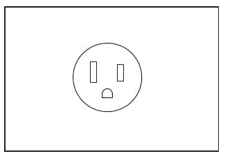
■ The charging environment
To ensure safe and reliable charging of the Subaru Solterra, the following charging conditions and equipment are recommended:
- Weatherproof outlet
When charging outdoors, connect the plug to a weather-resistant outlet and ensure that the connection remains protected from moisture at all times. - Dedicated circuit
- To minimize the risk of fire, use a dedicated circuit rated at least 15A with appropriate over-current protection, in accordance with the National Electric Code (ANSI/NFPA 70).
- To reduce the risk of electric shock, connect the Subaru Solterra to an outlet equipped with a Ground-Fault Circuit Interrupter (GFCI) or an Earth Leakage Circuit Breaker.
WARNING
■ Power sources precautions
Always observe the following precautions when selecting a power source for the Subaru Solterra.
Failure to follow these guidelines may result in fire, electric shock, or equipment damage, potentially causing severe injury or death.
- Connect only to a properly grounded AC 120 V outlet (NEMA 5-15R) equipped
with a GFCI and protected by a circuit breaker in accordance with local regulations.
A dedicated 15A circuit is strongly recommended for stable and safe charging.
- Do not connect the Subaru Solterra AC charging cable to power strips, multi-outlet adapters, or conversion plugs.
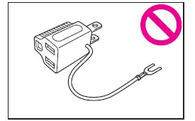
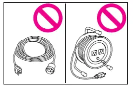
- Never use an extension cord when charging the Subaru Solterra. Extension
cords can overheat and typically lack integrated GFCI protection.
Additionally, the CCID (Charging Circuit Interrupting Device) safety functions may not operate correctly when using extension cords.
- Do not connect the charging system to a shared or branch outlet that is used by other devices.
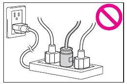
- Using a block heater outlet for charging the Subaru Solterra is strictly prohibited.
- Always connect the charging connector directly to the AC charging inlet. Do not use any type of adapter, converter, or extension between the charging connector and the vehicle inlet.
Following these guidelines ensures that the Subaru Solterra charging process remains safe, efficient, and compliant with electrical standards, while also protecting both the vehicle and the surrounding environment from potential hazards.
 Locking and unlocking AC charging connector
When the AC charging connector is properly inserted into the charging
inlet of the Subaru Solterra, it is automatically secured in place to prevent accidental
disconnection during the charging pro ...
 Charging methods
The Subaru Solterra supports multiple charging methods designed to
suit different driving needs and charging environments, allowing drivers to efficiently
replenish the traction battery in a varie ...
Other materials:
Child restraint system fixed with a seat belt
In the Subaru Solterra, a child restraint system for infants or small children
must be properly secured using the lap portion of the lap/shoulder seat belt. Correct
installation is essential to ensure that the system provides effective protection
in all driving conditions.
■ Installing chil ...
Windshield Wiper Arm And Blade Removal/Installation
1. Remove in the order indicated in the table.
1
Cap
2
Nut
3
Windshield wiper arm
(See Windshield Wiper Arm Installation Note.)
4
Windshield wiper blade
5
...
Operating Tips for WMA
WMA is short for Windows Media Audio
and is the audio compression format used
by Microsoft.
Audio data can be created and stored at a
higher compression ratio than MP3.
This unit plays files with the extension
(.wma) as WMA files.
Microsoft and Windows Media are
registered trademarks of ...
