Mazda 3 Service Manual: Drive Plate Removal/Installation [Fw6 A EL]
1. Remove the transaxle..
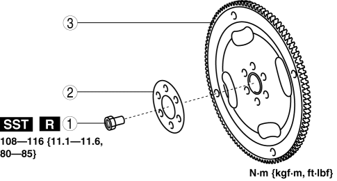
2. Remove in the order indicated in the table.
|
1 |
Drive plate installation bolts (See Drive Plate Installation Bolts Removal Note.) (See Drive Plate Installation Bolts Installation Note.) |
|
2 |
Backing plate |
|
3 |
Drive plate |
3. Install in the reverse order of removal.
Drive Plate Installation Bolts Removal Note
1. Set the SST
against the drive plate.
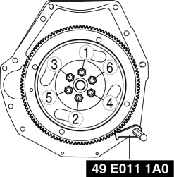
2. Loosen the drive plate installation bolts uniformly in two or three steps in the order shown in the figure, then remove the bolts and the drive plate.
Drive Plate Installation Bolts Installation Note
1. Set the SST
against the drive plate.
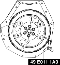
2. Tighten the new drive plate installation bolts uniformly in two or three steps in the order shown in the figure.
-
Tightening torque
-
108—116 N·m {11.1—11.8 kgf·m, 80—85 ft·lbf}
 Drive Plate Removal/Installation [FS5 A EL]
1. Remove the transaxle..
2. Remove in the order indicated in the table.
1
Drive plate installation bolts
(See Drive Plate Installation Bolts Removal Note.)
(See ...
 Electric Power Steering Oil Pump Component Disassembly/Assembly
CAUTION:
The internal parts of the EHPAS control module and motor could be damaged
if they receive an impact. Be careful when handling the EHPAS control module
and motor to prevent the c ...
Other materials:
Buckle Switch Inspection
Driver Side
1. Switch the ignition to off.
2. Disconnect the negative battery cable..
3. Remove the front seat..
4. Remove the front buckle..
5. Inspect for continuity between the buckle switch terminals using a tester.
If not as indicated in the table, replace the driver sid ...
Non Return Valve Inspection [Mzr 2.0, Mzr 2.5]
WARNING:
Fuel is very flammable liquid. If fuel spills or leaks from the pressurized
fuel system, it will cause serious injury or death and facility breakage. Fuel
can also irritate skin and eyes. To prevent this, always complete the “Fuel
Line Safety Procedure”, while referring ...
Steering SST
49 H032 301
Wrench
49 F017 1A0
Universal wrench
49 F032 303
Handle
49 B032 323
Rod seal remover body
49 N032 319A
Support plate
49 ...
