
Mazda 3 Service Manual: Joint Shaft Assembly [Skyactiv G 2.0]
1. Assemble in the order indicated in the table.
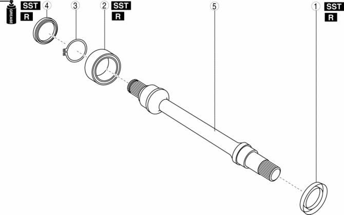
|
1 |
Dust cover . |
|
2 |
Bearing . |
|
3 |
Snap ring |
|
4 |
Dust seal . |
|
5 |
Joint shaft |
Dust Cover Assembly Note
1. Mark the position at the distance indicated in the figure from the end of the joint shaft.
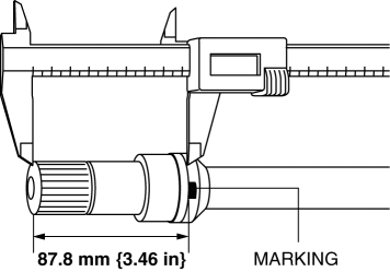
2. Using the SST
, install a new dust cover aligned to the marked position.
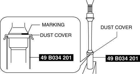
CAUTION:
-
Use the SST
with the notched surface facing down.
3. After installing, verify that the dust cover is installed within the specification.
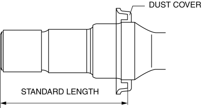
-
Standard length
-
87.0—88.0 mm {3.43—3.46 in}
Bearing Assembly Note
1. Install a new bearing using the SST
.
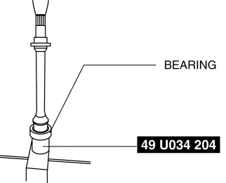
CAUTION:
-
Use the SST with the flat surface facing up.
Dust Seal Assembly Note
1. Apply grease to a new dust seal lip.
2. Mark the position at the distance indicated in the figure from the end of the joint shaft.
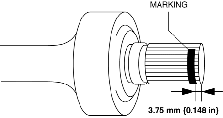
3. Set a new dust seal to the SST
, and press the dust seal into the joint shaft.
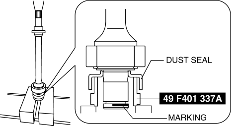
4. Press the dust seal with the mark on the joint shaft aligned.
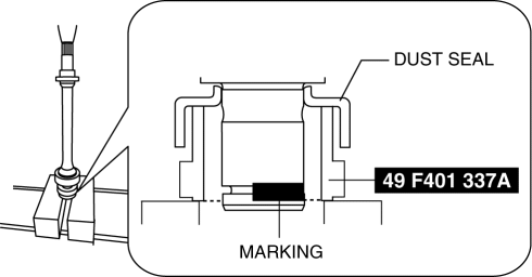
5. After installing, verify that the dust seal is installed within the specification.
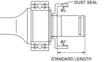
-
Standard length
-
38.75—39.55 mm {1.526—1.557 in}
 Joint Shaft Assembly [Mzr 2.3 Disi Turbo]
1. Assemble in the order indicated in the table.
1
Bracket
2
Dust seal (RH)
.
3
Bearing
.
4 ...
 Joint Shaft Disassembly [Mzr 2.0, Mzr 2.5]
1. Disassemble in the order indicated in the table.
1
Joint shaft component
.
2
Bearing
.
3
Dust seal (LH)
...
Other materials:
Rear seats
In the Subaru Solterra, rear seatbacks can be reclined or folded
using simple lever operations, providing flexibility for passenger comfort and cargo
space expansion.
Adjustment procedure
Pull the seatback angle adjustment lever A to adjust the angle of the Subaru
Solterra rear seatback.
...
Air Filter Removal/Installation [Mzr 2.0, Mzr 2.5]
Except for Mexico
1. Remove the fuel-filler pipe protector..
2. Remove in the order indicated in the table.
1
Evaporative hose
2
Air filter
3. Install in the reverse order of removal. ...
Advanced Park cancelation/ suspension
■ Assistance will be canceled when
Under the following conditions, the Subaru Solterra Advanced Park system will
automatically terminate its operation. When this occurs, immediately take control
by firmly holding the steering wheel and pressing the brake pedal to safely stop
the Subaru Solt ...
