
Mazda 3 Service Manual: PID/Data Monitor Inspection [Afs (Adaptive Front Lighting System)]
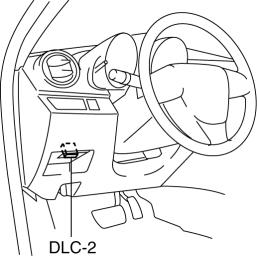
1. Connect the M-MDS (IDS) to the DLC-2.
2. After the vehicle is identified, select the following items from the initialization screen of the IDS.
a. Select “DataLogger”.
b. Select “Modules”.
c. Select “AFS”.
3. Select the applicable PID from the PID table.
4. Verify the PID data according to the directions on the screen.
NOTE:
-
The PID data screen function is used for monitoring the calculated value of input/output signals in the module. Therefore, if the monitored value of the output parts is not within the specification, it is necessary to inspect the monitored value of input parts corresponding to the applicable output part control. In addition, because the system does not display an output part malfunction as an abnormality in the monitored value, it is necessary to inspect the output parts individually.
-
When detecting DTCs, PIDs related to a malfunctioning system may not display even if the module is normal. Therefore, if a PID is not displayed, it is necessary to verify the DTC, perform malfunction diagnosis of the DTC that was detected, and do repairs.
 License Plate Light Removal/Installation
1. Disconnect the negative battery cable..
2. Remove the lens..
3. Insert a tape-wrapped fastener remover to the position shown in the figure,
release the tabs.
4. Pull the rear bumper in ...
 Parking Light Bulb Removal/Installation
1. Disconnect the negative battery cable..
2. Rotate the parking light socket in the direction of the arrow shown in the
figure to remove it.
3. Remove the parking light bulb.
4. Install i ...
Other materials:
Oil Pump Removal/Installation [Skyactiv G 2.0]
WARNING:
Hot engines and engine oil can cause severe burns. Turn off the engine and
wait until it and the engine oil have cooled.
A vehicle that is lifted but not securely supported on safety stands is dangerous.
It can slip or fall, causing death or serious injury. Never work ...
Pilot Bearing Inspection [G66 M R]
1. Perform the following procedures.
a. Remove the battery cover..
b. Disconnect the negative battery cable.
c. Remove the battery component. (ex: battery, battery tray and PCM component).
d. Remove the air cleaner component..
e. Remove the exhaust manifold insulator installation bolts an ...
Radio Reception
AM characteristics
AM signals bend around such things as
buildings or mountains and bounce off the
ionosphere.
Therefore, they can reach longer distances
than FM signals.
Because of this, two stations may
sometimes be picked up on the same
frequency at the same time.
FM characterist ...
