
Mazda 3 Service Manual: Pilot Bearing Inspection [A26 M R]
CAUTION:
-
Secure the steering wheel using tape or a cable to prevent the steering shaft from rotating after disconnecting the steering shaft. If the steering wheel rotates after the steering shaft and the steering gear and linkage are disconnected, the internal parts of the clock spring could be damaged.
NOTE:
-
Perform the pilot bearing inspection with the crankshaft or flywheel installed.
1. Perform the following procedures.
a. Remove the battery cover..
b. Disconnect the negative battery cable..
c. Remove the PCM cover No.1..
d. Disconnect the PCM connector..
e. Remove the battery tray and PCM component.
f. Remove the air cleaner component.
g. Remove the charge air cooler cover.
h. Remove the charge air cooler.
i. Remove the fuel pump resistor.
j. Remove the front tires.
k. Remove the splash shield.
l. Remove the aerodynamic under cover No.2.
m. Remove the WU-TWC bracket.
n. Remove the starter.
o. Remove the front auto leveling sensor.
p. Drain the transaxle oil into a suitable container..
q. Remove the manual transaxle..
r. Remove the clutch cover..
s. Remove the clutch disk..
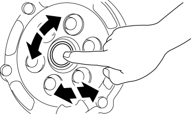
2. Inspect the rotation condition of the pilot bearing for damage or wear.
-
If there is any malfunction, replace the pilot bearing..
 On/Off Solenoid Removal/Installation [Fw6 A EL]
WARNING:
A hot transaxle and ATF can cause severe burns. Turn off the engine and wait
until they are cool.
Always wear protective eye wear when using the air compressor. If the ...
 Pilot Bearing Inspection [C66 M R]
1. Without removing the pilot bearing, turn the bearing while applying force
in the axial direction.
If there is any malfunction, replace the pilot bearing..
...
Other materials:
On Board Diagnostic System PID/Data Monitor Inspection [FS5 A EL]
NOTE:
The PID data screen function is used for monitoring the calculated value
of input/output signals in the module. Therefore, if the monitored value of
the output parts is not within the specification, it is necessary to inspect
the monitored value of input parts corresponding to ...
Headlight switch
In the Subaru Solterra, the headlight system can be controlled either
manually or automatically, offering flexibility and intelligent adaptation to changing
driving conditions.
Turning on the headlights
By operating
the switch, the lighting system of the Subaru Solterra activates in differ ...
Rear Bumper Disassembly/Assembly
1. Remove the License plate lights..
2. Disassemble in the order indicated in the table.
1
Fastener A
2
Bracket
3
Screw B
4
Reflector
(See Reflector Removal Note)
5 ...
