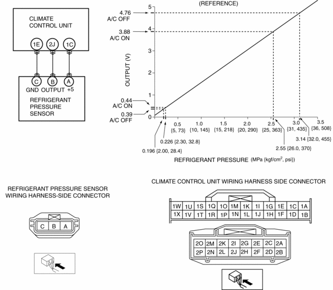
Mazda 3 Service Manual: Refrigerant Pressure Sensor Inspection [Full Auto Air Conditioner]
MZR 2.3 DISI Turbo, MZR 2.5
1. Install the manifold gauge.
2. Verify the high-pressure side reading of the manifold gauge.
3. Measure the terminal voltage of the climate control unit.
-
1C, 1E and 2J
4. Verify that below graph as measure the terminal voltage 2J.
5. Follow the climate control unit inspection when measure the other terminal voltage..
-
Terminal 1E: 1.0 V or less
-
Terminal 1C: Approx. 5 V (Ignition switch on)
-
If the each voltage is not normal, inspect the related wiring harness.
-
If there is any malfunction, replace the related wiring harness.
-
If wiring harness is normal, replace the refrigerant pressure sensor.
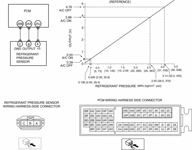
SKYACTIV-G 2.0
1. Install the manifold gauge.
2. Verify the high-pressure side reading of the manifold gauge.
3. Measure the terminal voltage of the PCM.
-
2BB, 2AX and 2AJ
4. Verify that below graph as measure the terminal voltage 2AX.
5. Follow the PCM inspection when measure the other terminal voltage..
-
Terminal 2BB: 1.0 V or less
-
Terminal 2AJ: Approx. 5 V (Ignition switch on)
-
If the each voltage is not normal, inspect the related wiring harness.
-
If there is any malfunction, replace the related wiring harness.
-
If wiring harness is normal, replace the refrigerant pressure sensor.
 Pressure Sensor Removal/Installation [Two Step Deployment Control System]
1. Switch the ignition to off.
2. Disconnect the negative battery cable and wait for 1 min or more..
3. Remove the inner garnish..
4. Remove the front door trim..
5. Remove the bolts.
6 ...
 Refrigerant Pressure Sensor Inspection [Manual Air Conditioner]
MZR 2.0, MZR 2.5
1. Install the manifold gauge.
2. Verify the high-pressure side reading of the manifold gauge.
3. Measure the terminal voltage of the climate control unit.
1G,1H and 2J
...
Other materials:
Quick Release Connector Removal/Installation [Mzr 2.0, Mzr 2.5]
WARNING:
Fuel is very flammable liquid. If fuel spills or leaks from the pressurized
fuel system, it will cause serious injury or death and facility breakage. Fuel
can also irritate skin and eyes. To prevent this, always complete the “Fuel
Line Safety Procedure”, while referring ...
PCM Inspection [Mzr 2.0, Mzr 2.5]
Using M-MDS
NOTE:
PIDs for the following parts are not available on this model. Go to the appropriate
part inspection page.
CMP sensor
Main relay
1. Connect the M-MDS to the DLC-2.
2. Switch the ignition to ON.
3. Measure the PID value.
...
Power Steering Fluid Inspection
Fluid Level Inspection
1. Verify that the fluid level is between MAX and MIN of the sub tank when the
engine is cold.
If the fluid is not at the specified level, adjust the fluid level (MIN-MAX
on sub tank) by adding/draining the fluid.
Power steering fluid type
Mazda Gen ...
