Mazda 3 Service Manual: Transaxle Fluid Temperature (Tft) Sensor Removal/Installation [FS5 A EL]
WARNING:
-
A hot transaxle and ATF can cause severe burns. Turn off the engine and wait until they are cool.
1. Remove the primary control valve body.
a. Remove the battery cover..
b. Disconnect the negative battery cable.
c. Remove the aerodynamic under cover NO.2..
d. Clean the transaxle exterior throughout with a steam cleaner or cleaning solvents.
e. Remove the air cleaner component..
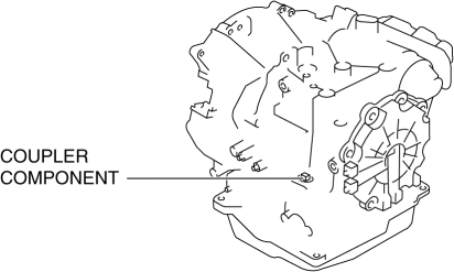
f. Disconnect the coupler component connector.

g. Drain the ATF..
h. Remove the oil pan.
i. Remove the primary control valve body..
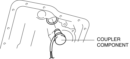
2. Remove the coupler component from transaxle case.

3. Remove the O-ring from the coupler component.
4. Install the primary control valve body.
a. Apply ATF to a new O-ring and install it on the coupler component.
b. Install the coupler component to transaxle case.
c. Connect the coupler component connector.
d. Install the primary control valve body..
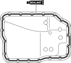
5. Apply a light coat of silicon sealant (TB1217E) to the contact surfaces of the oil pan and transaxle case.

CAUTION:
-
If any sealant remains on the sealing surfaces of the transaxle case and oil pan, transaxle damage may occur. Use a cleaning fluid to remove any old sealant from the transaxle case and oil pan.
6. Install the oil pan before the applied sealant starts to harden.
-
Tightening torque
-
6—8 N·m {62—81 kgf·cm, 54—70 in·lbf}
7. Add the ATF..
8. Install the aerodynamic under cover NO.2..
9. Install the air cleaner component..
10. Connect the negative battery cable.
11. Install the battery cover..
12. Perform the “Mechanical System Test”..
 Transaxle Fluid Temperature (Tft) Sensor Inspection [FS5 A EL]
CAUTION:
Water or foreign objects entering the connector can cause a poor connection
or corrosion. Be sure not to drop water or foreign objects on the connector
when disconnecting it.
...
 Transaxle Oil Inspection [A26 M R]
1. Park the vehicle on level ground.
2. Remove the aerodynamic under cover No.2..
3. Remove the oil level plug and gasket.
4. Verify that the oil is near the brim of the plug port.
I ...
Other materials:
System
The system operates only when the driver
is in the vehicle or within operational
range while the key is being carried.
NOTE
When the battery power is low, or in
places where there are high-intensity radio
waves or noise, the operational range
may become narrower or the system may
not operate ...
Air Filter Inspection [Mzr 2.3 Disi Turbo]
Airflow Inspection
1. Remove the air filter..
2. Blow from port A and verify that there is airflow from port B.
If there is no airflow, replace the air filter..
3. Blow from port B and verify that there is airflow from port A.
If there is no airflow, replace the air filt ...
Ignition Coil Inspection [Mzr 2.0, Mzr 2.5]
Ignition Coil Inspection
1. Perform the spark test and identify the malfunctioning cylinder..
2. Replace the ignition coil of the malfunctioning cylinder with that of a normal
cylinder, and perform the spark test again..
If the spark is not normal due to a malfunctioning ignition coil, ...
