
Mazda 3 Service Manual: After Service Precaution [Mzr 2.0, Mzr 2.5]
WARNING:
-
Fuel line spills and leakage are dangerous. Fuel can ignite and cause serious injuries or death and damage. When installing the fuel hose, perform “Fuel Leakage Inspection” described below.
-
A person charged with static electricity could cause a fire or explosion, resulting in death or serious injury. Before performing work on the fuel system, discharge static electricity by touching the vehicle body.
Fuel Leakage Inspection
Using M-MDS
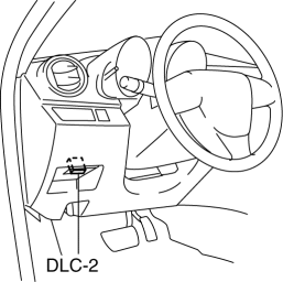
1. Connect the M-MDS to the DLC-2.
2. Switch the ignition to ON.
3. Using the simulation function “FP”, start the fuel pump..
4. Verify that there is no fuel leakage from the pressurized parts.
-
Standard
-
There shall be no leakage after 5 min.
5. In the case of fuel leakage, replace the following components and then do the recheck by the fuel leakage checking procedure.
-
If there is leakage, replace the fuel hoses and clips.
-
If there is damage on the seal on the fuel pipe side, replace the fuel pipe.
Without using M-MDS
1. Remove the battery cover..
2. Disconnect the negative battery cable..
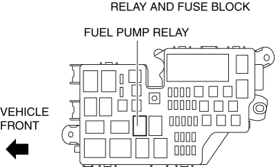
3. Remove the fuel pump relay.
CAUTION:
-
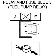
Short the specified terminals because shorting the wrong terminal of the relay and fuse block may cause malfunctions.
4. Using a jumper wire, short fuel pump relay terminals C and D in the relay and fuse block.
5. Connect the negative battery cable and operate the fuel pump..
6. Verify that there is no fuel leakage from the pressurized parts.
-
Standard
-
There shall be no leakage after 5 min.
7. In the case of fuel leakage, replace the following components and then do the recheck by the fuel leakage checking procedure.
-
If there is leakage, replace the fuel hoses and clips.
-
If there is damage on the seal on the fuel pipe side, replace the fuel pipe.
 Fuel
Fuel
...
 Before Service Precaution [Mzr 2.0, Mzr 2.5]
WARNING:
Fuel vapor is hazardous. It can very easily ignite, causing serious injury
and damage. Always keep sparks and flames away from fuel.
Fuel line spills and leakage from the p ...
Other materials:
Suspension SST
49 T034 1A0
Coil spring compressor set
49 0180 510B
Preload measuring attachment
49 B034 001
Guide
49 B034 002
Guide
49 T028 3A0
Ball joint puller set
...
Trunk Lid Stay Damper Disposal
NOTE:
The gas in the trunk lid stay damper is colorless, odorless, and non-toxic.
1. Wear protective eye wear.
2. Lay the trunk lid stay damper flat.
3. Hacksaw 2—3 mm {0.08—0.11 in} into the trunk lid stay damper
using a hacksaw, and allow the gas to escape from the trun ...
Front Seat Back Component [Vehicles Without Power Seat System] Removal/Installation
WARNING:
Handling a front seat (with built-in side air bag) improperly can accidentally
operate (deploy) the air bag, which may seriously injure you. Read the service
warnings before handling a front seat (with built-in side air bag)..
CAUTION:
After removing a front seat ...
