Mazda 3 Service Manual: Airflow Mode Main Link Removal/Installation
1. Set the air intake mode to FRESH.
2. Set the air mix mode to MAX COLD.
3. Disconnect the negative battery cable..
4. Remove the following parts:
a. Front doors.
b. Front scuff plate.
c. Front side trim.
d. Dashboard under cover.
e. Glove compartment.
f. Upper panel.
g. Shift lever knob (MTX).
h. Selector lever knob (ATX).
i. Shift panel.
j. Side wall.
k. Console.
l. Shift lever component (MTX).
m. Selector lever component (ATX).
n. Hood release lever from the lower panel.
o. Lower panel.
p. Knee bolster.
q. Driver-side air bag module.
r. Steering wheel.
s. Column cover.
t. Combination switch.
u. Joint cover.
v. Steering shaft.
w. Center panel.
x. Audio unit.
y. Climate control unit.
z. Instrument cluster.
aa. Center cover.
ab. Dashboard upper panel.
ac. Hole cover.
ad. Information display.
ae. A-pillar trim.
af. Windshield wiper arm and blade.
ag. Front fender molding.
ah. Cowl grille.
ai. Windshield wiper motor.
aj. Rear heat duct (1).
ak. Shower ducts.
al. Heater case.
5. Remove the nuts and bolts for installing the dashboard to the body.
6. Remove the nuts and bolts for installing the A/C unit to the dashboard.
7. Remove the accelerator pedal..
8. Disconnect the following connectors:
-
Blower motor connector
-
Power MOS FET connector (Full-auto air conditioner)
-
Resistor connector (Manual air conditioner)
-
Evaporator temperature sensor connector
-
Air intake actuator connector
-
Air mix actuator connector (Full-auto air conditioner)
-
Airflow mode actuator connector (Full-auto air conditioner)
9. Remove the dashboard..
10. Remove the airflow mode actuator (Full-auto air conditioner).
11. Remove the airflow mode rod (Manual air conditioner).
12. Remove the screw.
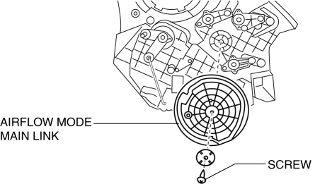
13. Remove the airflow mode main link.
14. Install in the reverse order of removal.
Airflow Mode Main Link Installation Note
CAUTION:
-
Apply only the specified grease to links. Otherwise abnormal noise or improper operation may result.
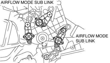
Full-auto air conditioner
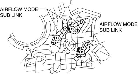
1. Set the airflow mode sub link to the A/C unit as shown in the figure.
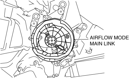
2. Set the airflow mode main link to the A/C unit as shown in the figure.
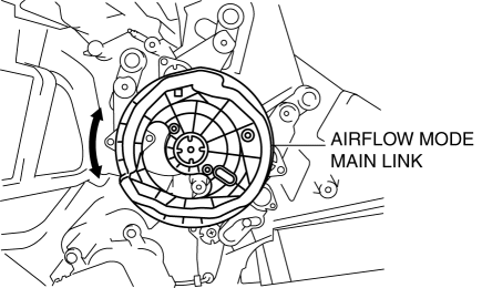
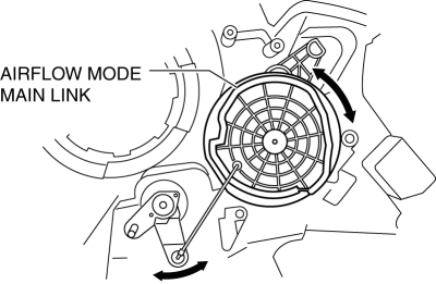
3. Press the airflow mode main link lightly to the A/C unit it in the direction shown by the arrow, then set the projections of each airflow mode sub link into the grooves of the airflow mode main link.
4. Rotate airflow mode main link and verify that each mode is accessed properly.
Manual air conditioner
1. Set the airflow mode sub link to the A/C unit as shown in the figure.
2. Set the airflow mode main link to the A/C unit as shown in the figure.
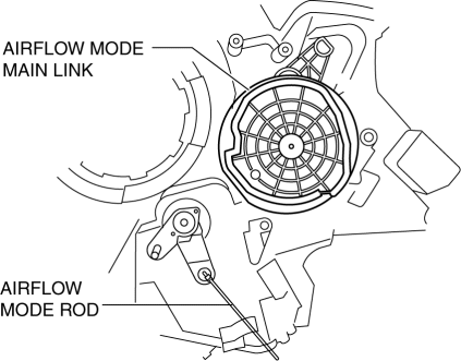
3. Install the airflow mode rod.
4. Press the airflow mode main link lightly to the A/C unit it in the direction shown by the arrow, then set the projections of each airflow mode sub link into the grooves of the airflow mode main link.
5. Rotate airflow mode main link and verify that each mode is accessed properly.
 Air Filter Removal/Installation [Skyactiv G 2.0]
1. Remove the fuel-filler pipe protector..
2. Remove in the order indicated in the table.
1
Evaporative hose
2
Air filter
3. Ins ...
 HVAC SST
49 B061 014
Spring Lock Coupling Disconnect Tool
49 G061 001
Spring Lock Coupling Disconnect Tool
49 B061 015A
Holder
...
Other materials:
Air Filter Inspection [Mzr 2.3 Disi Turbo]
Airflow Inspection
1. Remove the air filter..
2. Blow from port A and verify that there is airflow from port B.
If there is no airflow, replace the air filter..
3. Blow from port B and verify that there is airflow from port A.
If there is no airflow, replace the air filt ...
Front Door Module Panel Removal/Installation
1. To access the glass installation bolt, position the front door glass so that
the distance from the top of the front door glass to the upper part of the front
beltline molding is approx. 80 mm {3.1 in}.
2. Disconnect the negative battery cable..
3. Remove the following parts:
a. Inne ...
Condenser Inspection
1. Inspect the condenser for cracks, damage, and oil leakage.
If there is any malfunction, replace the condenser.
2. Visually inspect the fins for clogging of foreign material.
If any fins are clogged, remove the foreign material.
3. Visually inspect for bent fins.
...
