Mazda 3 Service Manual: Blower Motor Removal [Full Auto Air Conditioner]
NOTE:
-
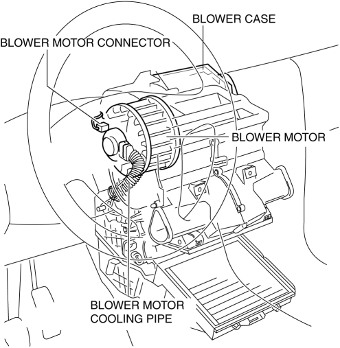
The blower motor is located on the A/C unit as shown in the figure.
-
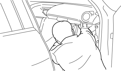
Perform the work from the front passenger side in the posture shown in the figure.
1. Set the air intake mode to FRESH.
2. Disconnect the negative battery cable.
3. Remove the following parts:
a. Front scuff plate.
b. Front side trim.
c. Upper panel.
d. Shift lever knob (MTX).
e. Selector lever knob (ATX).
f. Shift panel.
g. Side wall.
h. Console.
i. Dashboard under cover.
j. Glove compartment.
k. Hood release lever.
l. Lower panel.
m. Shower duct (Passenger-side).
n. Accelerator pedal.
4. Disconnect the air intake actuator connector..
5. Detach the harness clip from the blower case.
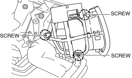
6. Remove the screws shown in the figure and slide the blower case.
7. Remove the blower case.
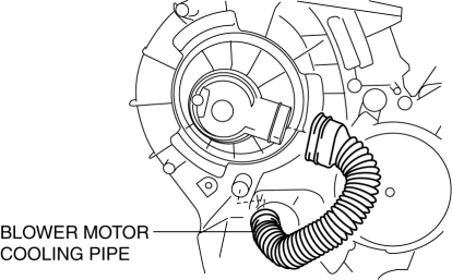
8. Disconnect the blower motor cooling pipe.
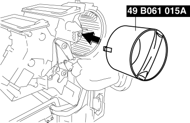
9. Install the SST (49 B061 015A)
to the blower motor.
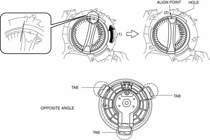
a. Rotate the SST
(1) and align the SST
hole with the align point (2) and then confirm that the SST
tabs into the three set holes on the blower motor they are inserted as shown in the figure.
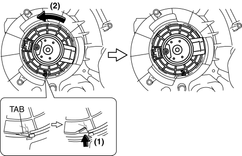
10. Press the tab (1) and rotate the blower motor (2) and push the blower motor into the A/C case slightly.
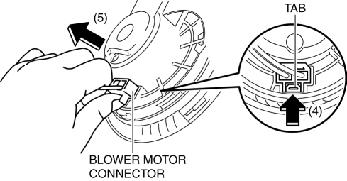
11. Rotate the blower motor and the blower motor connector position as shown in the figure (3) for disconnect the blower motor connector eased.
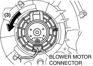
12. Press the tab (4) and disconnect the blower motor connector as shown in the figure (5).
13. Remove the blower motor in the direction shown by the arrow.
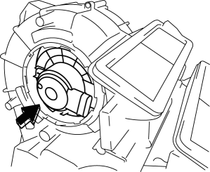
CAUTION:
-
To prevent damage to the sirocco fan, pull the blower motor out being careful that the blower motor does not interfere with the A/C unit.
14. Remove the blower motor with SST (49 B061 015A)
by pulling it out.
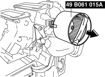
CAUTION:
-
To prevent damage to the sirocco fan, pull the blower motor out being careful that the blower motor does not interfere with the A/C unit.
 Blower Motor Installation [Full Auto Air Conditioner]
1. Install the SST (49 B061 015A) to the blower motor.
2. Install the blower motor with the SST (49 B061 015A) installed, to
the A/C unit.
CAUTION:
To prevent damage to the siroc ...
 Blower Motor Removal [Manual Air Conditioner]
NOTE:
The blower motor is located on the A/C unit as shown in the figure.
Perform the work from the front passenger side in the posture shown in the
figure.
1. Set ...
Other materials:
Installing Child-Restraint Systems
Accident statistics reveal that a child is
safer in the rear seat. The front passenger's
seat is clearly the worst choice for any
child under 12, and with rear-facing childrestraint
systems it is clearly unsafe due to
air bags.
NOTE
Even if your vehicle is equipped with front passenger seat w ...
Parking Brake
CAUTION
Driving with the parking brake on
will cause excessive wear of the brake
parts.
NOTE
For parking in snow, refer to Winter Driving regarding parking
brake use.
Setting the parking brake
Depress the brake pedal and then firmly
pull the parking brake lever fully upwar ...
Wheel Balance Adjustment
CAUTION:
Adjust the outer wheel balance first, then the inner wheel balance.
Be careful not to scratch the wheels.
Adhesive-type Balance Weight (Outer)
1. Remove the old balance weight from the wheel.
2. Remove the double-sided adhesive tape remaining on the wheel, then clea ...
