
Mazda 3 Service Manual: Brake Fluid Pressure Sensor Inspection
1. Switch the ignition to off.
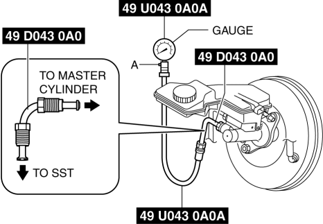
2. Install the SSTs
to the master cylinder (secondary side) as shown in the figure.
NOTE:
-
When installing the SST
(49 D043 0A0) to the master cylinder, use a commercially available flare nut wrench (flare nut across flat 12 mm {0.47 in}
).
3. Bleed the brake line and the SSTs
of air. (Bleed the SSTs
of air using air bleed valve A.)
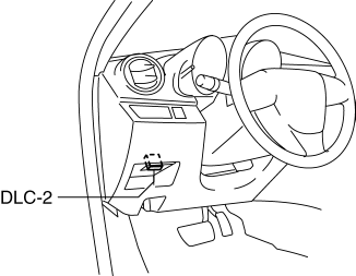
4. Connect the M-MDS to the DLC-2.
5. Select the “MCYLI_P” PID..
6. Start the engine.
7. Depress the brake pedal, and verify that the fluid pressure value of the SST
(gauge) and the value shown on the M-MDS are equal.
-
If the fluid pressure values are different, replace the DSC HU/CM..
 Warm Up Three Way Catalytic Converter (Wu Twc) Inspection [Mzr 2.0, Mzr 2.5]
CAUTION:
Perform the following procedures, DTC P0421:00 is indicated only.
1. Connect the M-MDS to the DLC-2.
2. Start the engine and warm it up to normal operating temperature.
...
 Pressure Sensor Removal/Installation [Two Step Deployment Control System]
1. Switch the ignition to off.
2. Disconnect the negative battery cable and wait for 1 min or more..
3. Remove the inner garnish..
4. Remove the front door trim..
5. Remove the bolts.
6 ...
Other materials:
Opening the Hood
With the vehicle parked, pull the
release handle to unlock the hood.
Insert your hand into the hood opening,
slide the latch lever to the right, and lift
up the hood.
NOTE
The lever is located a little to the left of
center when facing the vehicle.
Grasp the support r ...
Oil Pressure Inspection [Mzr 2.0, Mzr 2.5]
WARNING:
Hot engines and engine oil can cause severe burns. Turn off the engine and
wait until it and the engine oil have cooled.
A vehicle that is lifted but not securely supported on safety stands is dangerous.
It can slip or fall, causing death or serious injury. Never work ...
Precaution [ABS]
1. Any one or a combination of the ABS warning and brake system warning lights
illuminates even when the system is normal.
Warning lights that may illuminate and/or flash
Cases in which the light may illuminate
Conditions in which the light will go ou ...
