Mazda 3 Service Manual: Clock Spring Inspection [Two Step Deployment Control System]
1. Disconnect the negative battery cable..
2. Remove the driver–side air bag module..
3. Remove the steering wheel..
4. Remove the column cover.
5. Remove the clock spring..
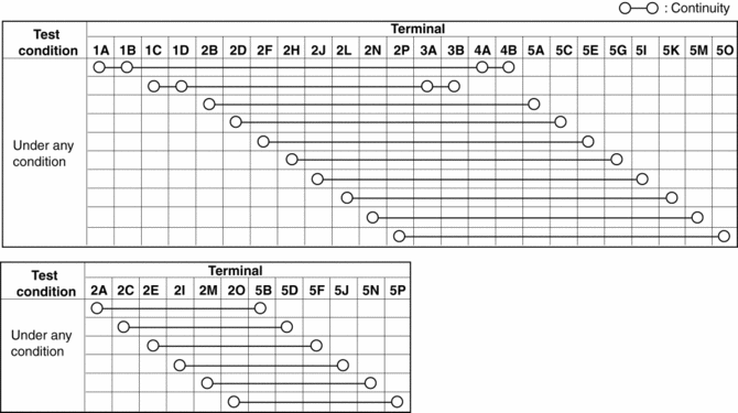
6. Verify that the continuity is as indicated in the table.
-
If not as indicated in the table, replace the clock spring.
NOTE:
-
When the vehicle-side connector for the clock spring is disconnected, terminals 1A, 1B, 1C and 1D are shorted to prevent unexpected operation (deployment) of the air bag module.
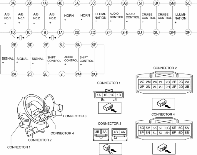
Vehicles with steering switch
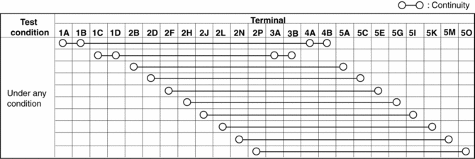
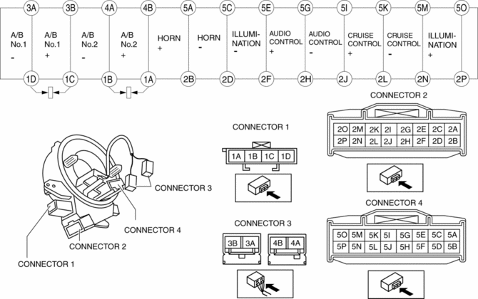
Vehicles without steering switch
 Clock Spring Inspection [Standard Deployment Control System]
1. Disconnect the negative battery cable..
2. Remove the driver–side air bag module..
3. Remove the steering wheel..
4. Remove the column cover.
5. Remove the clock spring..
6. Verify that ...
 Control System Personalization Features Setting Procedure
1. Connect the M-MDS to the DLC-2.
2. After the vehicle is identified, select the following items from the initial
screen of the M-MDS.
When using the IDS (laptop PC)
Sele ...
Other materials:
Operating Tips for OGG
OGG is the audio compression format for
Xiph. Org Foundation.
Audio data can be created and stored at a
higher compression ratio than MP3.
This unit plays files with the extension
(.ogg) as OGG files.
CAUTION
Do not use an audio fi le extension on
fi les other than audio fi le ...
Glass Antenna Inspection
4SD
1. Disconnect the negative battery cable..
2. Disconnect the antenna amplifier connector B..
3. Disconnect the antenna feeder No.3 connector C. (with audio unit (with display)).
4. Inspect the glass antenna for damage visually.
5. Inspect for continuity between the glass antenna termin ...
Rear Door Hinge Removal/Installation
1. Disconnect the negative battery cable..
2. Remove the following parts:
a. Rear door.
b. Front scuff plate.
c. Rear scuff plate.
d. B-pillar lower trim.
3. Remove in the order indicated in the table.
1
Bolt
2
Nut
...
