
Mazda 3 Service Manual: Discharge Headlight Service Warnings
Discharge Headlight Service Warnings
-
To prevent electrical shock when replacing the discharge headlight bulb, always perform the servicing with dry hands and in an area where it does not get wet.
-
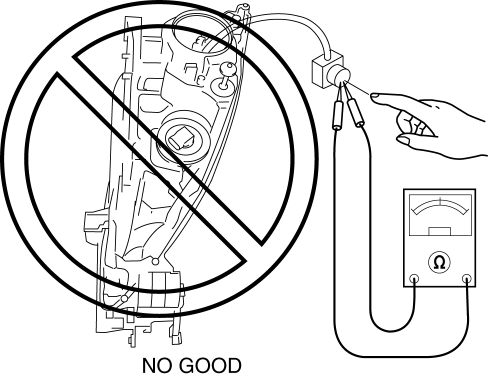
Never probe the discharge headlight bulb connector directly with a finger or tester. Otherwise, it could result in electrical shock. When the light switch is ON, high voltage of approx. 25,000 V flows the discharge headlight bulb connector.
-
When the headlights are on, high voltage flows around the discharge headlight bulb and discharge headlight bulb connector. When servicing the discharge headlights while they are illuminated, always perform the servicing with the headlights in their installed condition.
Discharge Headlight Control Module Service Warnings
-
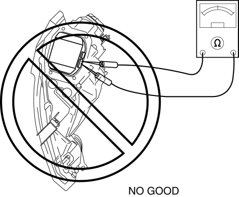
Do not use a tester to inspect or disassemble a discharge headlight control module. Otherwise, it could result in electrical shock.
Discharge Headlight Control Module Reuse
-
If the discharge headlight control module is damaged, replace the module with a new one. Otherwise, it could result in electrical shock or operation malfunction.
-
The discharge headlight control module may temporarily operate normally even though it may have been hit, however, the inside of the module could be damaged. If the control module is reused, inspect the following items related to the discharge headlight bulb illumination, and verify that there is no malfunction.
-
Perform the tests for the discharge headlight bulb several times under cold lighting condition (switch on after switching discharge headlight bulb off for approx. 10 min or more) and under warm-up lighting condition (switch off for approx. 1 min after switching discharge headlight bulb on for approx. 15 min or more, and switch on), and verify that the discharge headlight bulb illuminates.
-
Inspect the discharge headlight bulb illumination until it illuminates evenly after cold lighting, verify that the discharge headlight bulb illumination has no flicker or uneven brightness level.
-
Illuminate the headlight for approx. 30 min using a proper discharge headlight bulb, and verify that the illumination condition is stabilized on the left and right with no difference in brightness level.
 Discharge Headlight Control Module Removal/Installation
CAUTION:
Incorrect servicing of the discharge headlights could result in electrical
shock. Before servicing the discharge headlights, always refer to the discharge
headlight service warn ...
 Discharge Headlight System Inspection
Discharge headlight inoperative
WARNING:
Incorrect servicing of the discharge headlight bulb could result in electrical
shock. Before servicing the discharge headlight bulb, always refer t ...
Other materials:
Customization
In the Subaru Solterra, a variety of system parameters can be adjusted to better
match driver preferences, offering enhanced comfort, usability, and personalization
of vehicle functions.
WARNING
■ Back door closer
If the Subaru Solterra back door is left slightly ajar, the integrated
...
Advanced Park
Function description
The Advanced Park system in the Subaru Solterra is designed to deliver a refined
and highly controlled parking experience by assisting the driver during both parking
and exiting maneuvers. Using a combination of sensors and cameras, the Subaru Solterra
provides a comprehe ...
Electric Variable Valve Timing Motor/Driver Inspection [Skyactiv G 2.0]
WARNING:
A hot engine can cause severe burns. Turn off the engine and wait until it
is cool before servicing.
CAUTION:
Do not disassemble the electric variable valve timing motor/driver because
it is a precision unit.
1. Remove the battery cover..
2. Disconnect th ...
