Mazda 3 Service Manual: Hydraulic Variable Valve Timing Actuator Inspection [Skyactiv G 2.0]
WARNING:
-
A hot engine can cause severe burns. Turn off the engine and wait until it is cool before servicing.
CAUTION:
-
Do not disassemble the hydraulic variable valve timing actuator because it is a precision unit.
1. Remove the battery cover..
2. Disconnect the negative battery cable..
3. Remove the plug hole plate..
4. Remove the ignition coil/ion sensors..
5. Remove the cylinder head cover..
6. Verify that the notch of the rotor and projection of the cover on the hydraulic variable valve timing actuator are aligned and fitted.
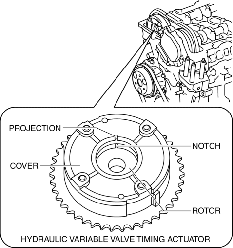
-
If the notch of the rotor and projection of the cover are not aligned, rotate the crankshaft in the direction the engine rotates two turns and verify that they are aligned.
-
If the notch of the rotor and projection of the cover are still not aligned, replace the hydraulic variable valve timing actuator..
-
If, when turning the crankshaft, there is a hitting noise from the hydraulic variable valve timing actuator each time before the cam reaches its maximum lift, it means that the actuator is not secured. Replace the hydraulic variable valve timing actuator..
7. Install in the reverse order of removal.
 Variable Valve Timing Actuator Removal/Installation [Mzr 2.3 Disi Turbo]
WARNING:
Fuel vapor is hazardous. It can very easily ignite, causing serious injury
and damage. Always keep sparks and flames away from fuel.
Fuel line spills and leakage are danger ...

Other materials:
Variable Intake Air Solenoid Valve Inspection [Mzr 2.0, Mzr 2.5]
Airflow Inspection
1. Remove the battery cover..
2. Disconnect the negative battery cable..
3. Remove the variable intake air solenoid valve..
4. Inspect airflow between the ports under the following conditions.
If not as specified, replace the variable intake air solenoid val ...
Advanced Park cancelation/ suspension
■ Assistance will be canceled when
Under the following conditions, the Subaru Solterra Advanced Park system will
automatically terminate its operation. When this occurs, immediately take control
by firmly holding the steering wheel and pressing the brake pedal to safely stop
the Subaru Solt ...
Settings
NOTE
Depending on the grade and specification, the screen display may differ.
Select the icon on the home
screen and display the Settings screen.
Switch the tab and select the setting item you want to change.
You can customize settings in the setup display as follows:
Tab
...
