Mazda 3 Service Manual: Rear Trailing Link Removal/Installation
CAUTION:
-
Performing the following procedures without first removing the ABS wheel-speed sensor may possibly cause an open circuit in the wiring harness if it is pulled by mistake. Before performing the following procedures, disconnect the ABS wheel-speed sensor wiring harness connector (axle side) and fix the wiring harness to an appropriate place where it will not be pulled by mistake while servicing the vehicle.
1. Disconnect the auto leveling sensor link lower side. (Vehicles with AFS).
2. Remove the rear coil spring..
3. Remove in the order indicated in the table.
4. Install in the reverse order of removal.
5. Inspect the wheel alignment and adjust it if necessary..
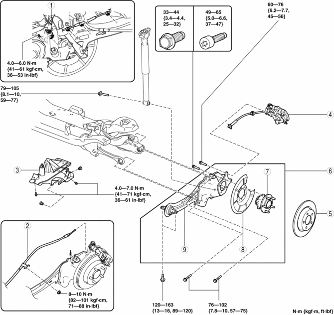
|
1 |
Rear ABS wheel-speed sensor wiring harness (See Rear ABS Wheel-speed Sensor Wiring Harness Installation Note.) |
|
2 |
Rear parking brake cable |
|
3 |
Under cover |
|
4 |
Brake caliper component . |
|
5 |
Disc plate |
|
6 |
Rear trailing link component (See Rear Trailing Link Component Removal Note.) (See Rear Trailing Link Component Installation Note.) |
|
7 |
Rear wheel hub component |
|
8 |
Dust cover |
|
9 |
Rear trailing link |
Brake Caliper Component Removal Note
1. Remove the brake caliper component and suspend it out of the way using a cable.
Rear Trailing Link Component Removal Note
WARNING:
-
Removing the rear trailing link component is dangerous. The rear trailing link component could fall and cause serious injury or death. Verify that the jack securely supports the rear trailing link component.
1. Support the rear trailing link component using a jack.
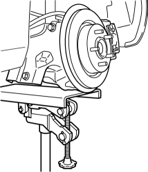
2. Remove the rear trailing link front side bolts.
3. Remove the rear shock absorber lower side bolt.
4. Remove the rear lateral link outer side bolt.
5. Remove the rear upper arm outer side bolt.
6. Remove the rear trailing link component.
Rear Trailing Link Component Installation Note
WARNING:
-
Installing the rear trailing link component is dangerous. The rear trailing link component could fall and cause serious injury or death. Verify that the jack securely supports the rear trailing link component.
1. Support the trailing link component using a jack.
2. Install the rear upper arm outer side bolt.
3. Install the rear lateral link outer side bolt.
4. Install the rear shock absorber lower side bolt.
5. Tighten the trailing link front side bolts.
Rear ABS Wheel-speed Sensor Wiring Harness Installation Note
1. Pass the rear ABS wheel-speed sensor wiring harness outside the rear parking brake cable as shown in the figure.
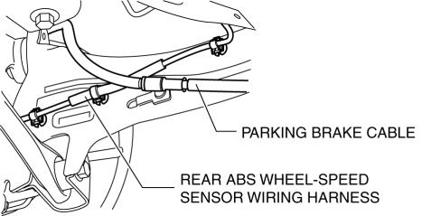
2. Install the rear ABS wheel-speed sensor wiring harness.
 Precaution
Intermittent Concern Troubleshooting
Vibration method
If malfunction occurs or becomes worse while driving on a rough road or when
the engine is vibrating, perform the steps below.
NO ...
 Rear Wheel Hub Bolt Replacement
1. Remove the brake calliper component and disc plate..
2. Remove the wheel hub bolt using the SST as shown in the figure.
3. Place a new wheel hub bolt in the wheel hub.
4. Install the whee ...
Other materials:
Front Seat Rail Guide Cover Removal/Installation
WARNING:
Handling a front seat (with built-in side air bag) improperly can accidentally
operate (deploy) the air bag, which may seriously injure you. Read the service
warnings before handling a front seat (with built-in side air bag)..
CAUTION:
After removing a front seat ...
Refrigerant Pressure Sensor Inspection [Manual Air Conditioner]
MZR 2.0, MZR 2.5
1. Install the manifold gauge.
2. Verify the high-pressure side reading of the manifold gauge.
3. Measure the terminal voltage of the climate control unit.
1G,1H and 2J
4. Verify that below graph as measure the terminal voltage 2J.
5. Follow the climate control ...
Variable Swirl Shutter Valve Actuator Inspection [Mzr 2.3 Disi Turbo]
Operation Inspection
1. Remove the air hose..
2. Disconnect the vacuum hose from the variable swirl control solenoid valve.
3. Connect a vacuum pump to the variable swirl shutter valve actuator.
4. Apply vacuum and verify that the rod moves.
Vacuum
kPa {mmHg, inHg ...
