Mazda 3 Service Manual: Steering Wheel And Column Removal/Installation [Without Advanced Keyless Entry And Push Button Start System]
WARNING:
-
Handling the air bag module improperly can accidentally operate (deploy) the air bag module, which may seriously injure you. Read the service warnings before handling the air bag module..
1. Remove the driver-side front scuff plate..
2. Remove the driver-side front side trim..
3. Remove the hood release lever..
4. Remove the upper panel..
5. Remove the shift knob (MTX)..
6. Remove the selector lever knob (ATX)..
7. Remove the shift panel..
8. Remove the side wall..
9. Remove the console..
10. Remove the lower panel..
11. Remove in the order indicated in the table.
12. Install in the reverse order of removal.
|
1 |
Driver-side air bag module (See DRIVER-SIDE AIR BAG MODULE REMOVAL/INSTALLATION [STANDARD DEPLOYMENT CONTROL SYSTEM].) (See DRIVER-SIDE AIR BAG MODULE REMOVAL/INSTALLATION [TWO-STEP DEPLOYMENT CONTROL SYSTEM].) |
|
2 |
Lockbolt |
|
3 |
Steering wheel (See Steering Wheel Removal Note.) (See Steering Wheel Installation Note.) |
|
4 |
Column cover (See COLUMN COVER REMOVAL/INSTALLATION.) |
|
5 |
Clock spring, combination switch (See CLOCK SPRING REMOVAL/INSTALLATION.) (See COMBINATION SWITCH REMOVAL/INSTALLATION.) |
|
6 |
Key cylinder (See Key Cylinder Removal Note.) (See Key Cylinder Installation Note.) |
|
7 |
Coil antenna (See COIL ANTENNA REMOVAL/INSTALLATION.) |
|
8 |
Ignition switch (See IGNITION SWITCH REMOVAL/INSTALLATION [WITHOUT ADVANCED KEYLESS ENTRY AND PUSH BUTTON START SYSTEM].) |
|
9 |
Joint cover |
|
10 |
Joint bolt (See Joint Bolt Installation Note.) |
|
11 |
Steering shaft component (See Steering Shaft Component Installation Note.) |
|
12 |
Steering lock mounting bolt (See Steering Lock Mounting Bolt, Steering Lock Removal Note.) (See Steering Lock, Steering Lock Mounting Bolt Installation Note.) |
|
13 |
Steering lock (See Steering Lock Mounting Bolt, Steering Lock Removal Note.) (See Steering Lock, Steering Lock Mounting Bolt Installation Note.) |
|
14 |
Steering shaft |
Steering Wheel Removal Note
CAUTION:
-
Do not try to remove the steering wheel by hitting the shaft with a hammer. The column will be damaged.
1. Set the wheels in the straight-ahead position.
2. Remove the steering wheel using any commercially available puller.
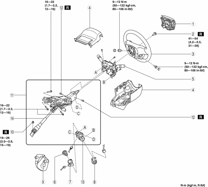
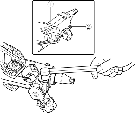
Key Cylinder Removal Note
1. Insert the key into the key cylinder and turn it to the ACC position.
2. Insert a pin from the position indicated by the arrow in the figure, and while pressing the lock bar with the pin, remove the key cylinder from the steering lock component.
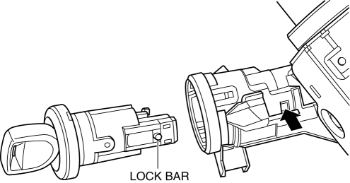
Steering Lock Mounting Bolt, Steering Lock Removal Note
1. Make a groove in the heads of the steering lock mounting bolts using a chisel and hammer.
2. Remove the steering lock.
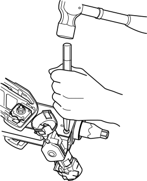
Steering Lock, Steering Lock Mounting Bolt Installation Note
1. Assemble area A of the steering lock to area B of the steering shaft, and press the steering lock in the direction of the arrow in the figure until it contacts the steering shaft.
2. Temporarily install the steering lock to the steering shaft using a new steering lock mounting bolt.
3. Tighten the steering lock mounting bolts in the order shown in the figure until the heads break off.
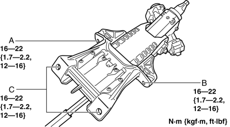
Steering Shaft Component Installation Note
1. Verify that the adjusting lever is in the LOCK position.
2. Tighten the bolts in alphabetical order.
Joint Bolt Installation Note
1. Install the steering shaft component to the steering gear.
2. After temporarily install the joint bolt to the intermediate shaft joint, verify that the joint bolt is installed to the groove of the steering gear.
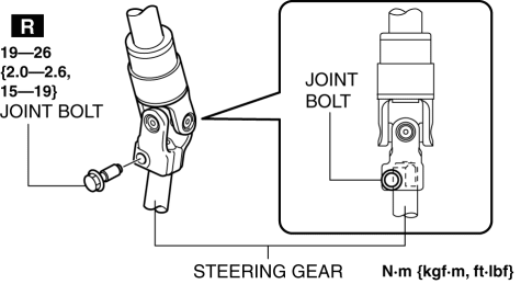
3. Tighten the joint bolt to the specified torque.
Key Cylinder Installation Note
1. Insert the key into the key cylinder and turn it to the ACC position.
2. Install the key cylinder to the steering lock.
Steering Wheel Installation Note
1. Set the wheels in the straight-ahead position and install the steering wheel.
 Steering Wheel And Column Removal/Installation [With Advanced Keyless Entry
And Push Button Start System]
Steering Wheel And Column Removal/Installation [With Advanced Keyless Entry
And Push Button Start System]
WARNING:
Handling the air bag module improperly can accidentally operate (deploy)
the air bag module, which may seriously injure you. Read the service warnings
before handling the air ba ...
 Combination Switch Disassembly/Assembly
CAUTION:
Handling the air bag module improperly can accidentally deploy the air bag
module, which may seriously injure you. Read the air bag system service warnings
and cautions before h ...
Other materials:
Rear Door Trim Disassembly/Assembly
1. Disassemble in the order shown in the figure.
1
Screw
2
Assist handle
3
Switch panel cover
4
Power window subswitch
5
Rear door trim
2. Assembl ...
Engine Coolant
Inspecting Coolant Level
WARNING
Do not use a match or live fl ame in the
engine compartment. DO NOT ADD
COOLANT WHEN THE ENGINE IS HOT:
A hot engine is dangerous. If the
engine has been running, parts of the
engine compartment can become very
hot. You could be burned. C ...
Shift Lock System Inspection
Shift-Lock System Inspection
1. Switch the ignition to ON.
2. Shift the selector lever to the P position.
3. Perform the following procedures to inspect the shift-lock system.
If there is any malfunction, inspect the shift-lock solenoid and P position
switch..
a. Verify that th ...
