Mazda 3 Service Manual: TCM Inspection [FS5 A EL]
NOTE:
-
The TCM terminal voltage can vary with conditions when measuring and changes due to age deterioration on the vehicle, causing false diagnosis. Therefore a comprehensive inspection of the input and output systems, and the TCM is necessary to determine where the malfunction occurs.
1. Connect the voltmeter (-) lead to body GND.
2. Measure the voltage at each terminal.
-
If any incorrect voltage is detected, inspect the related system(s), wiring harnesses and connector(s) referring to the “Inspection Item” column in the “TCM Terminal Voltage”.
TCM Terminal Voltage (Reference)
|
Terminal |
Connected to |
Test Condition |
Voltage (V) |
Inspection Item |
|
A |
— |
— |
— |
— |
|
B |
CAN module |
Because this terminal is for CAN, no valid determination of terminal voltage is possible. |
||
|
C |
— |
— |
— |
— |
|
D |
— |
— |
— |
— |
|
E |
CAN module |
Because this terminal is for CAN, no valid determination of terminal voltage is possible. |
||
|
F |
Down switch |
Selector lever down-shift position |
Below 1.0 |
|
|
Except selector lever down-shift position |
B+ |
|||
|
G |
Up switch |
Selector lever up-shift position |
Below 1.0 |
|
|
Except selector lever up-shift position |
B+ |
|||
|
H |
— |
— |
— |
— |
|
I |
AT main relay |
Ignition switch off |
Below 1.0 |
|
|
Ignition switch ON |
B+ |
|||
|
J |
Battery |
Under any condition |
B+ |
|
|
K |
M position switch |
M position |
Below 1.0 |
|
|
Except M position |
B+ |
|||
|
L |
GND |
Under any condition |
Below 1.0 |
|
|
M |
GND |
Under any condition |
Below 1.0 |
|
|
N |
— |
— |
— |
— |
|
O |
AT main relay |
Ignition switch off |
Below 1.0 |
|
|
Ignition switch ON |
B+ |
|||
|
P |
AT main relay |
Ignition switch off |
Below 1.0 |
|
|
Ignition switch ON |
B+ |
|||
|
Q |
— |
— |
— |
— |
|
R |
— |
— |
— |
— |
|
S |
Oil pressure switch |
1GR |
Below 1.0 |
|
|
2GR |
Below 1.0 |
|||
|
3GR |
Below 1.0 |
|||
|
4GR |
B+ |
|||
|
5GR |
B+ |
|||
|
T |
— |
— |
— |
— |
|
U |
TR switch |
Selector lever at P position |
4.3—4.8 |
|
|
Selector lever at R position |
3.8—4.2 |
|||
|
Selector lever at N position |
3.0—3.5 |
|||
|
Selector lever at D position |
2.2—2.7 |
|||
|
Selector lever at M position |
2.2—2.7 |
|||
|
V |
TR switch, TFT sensor |
Under any condition |
Below 1.0 |
|
|
W |
— |
— |
— |
— |
|
X |
— |
— |
— |
— |
|
Y |
Input/turbine speed sensor (-) |
(See Input/turbine speed sensor.) |
|
|
|
Z |
VSS |
(See VSS.) |
|
|
|
AA |
TFT sensor |
ATF temperature 20 °C {68 °F} |
Approx.3.3 |
|
|
ATF temperature 65 °C {149 °F} |
Approx.1.3 |
|||
|
AB |
Input/turbine speed sensor (+) |
(See Input/turbine speed sensor.) |
|
|
|
AC |
Intermediate sensor |
(See Intermediate sensor.) |
|
|
|
AD |
Pressure control solenoid A (+) |
(See Pressure control solenoid A (+).) |
|
|
|
AE |
Pressure control solenoid A (-) |
(See Pressure control solenoid A (-).) |
|
|
|
AF |
— |
— |
— |
— |
|
AG |
Shift solenoid A |
(See Shift solenoid A.) |
|
|
|
AH |
Shift solenoid D |
1GR at D position |
Below 1.0 |
|
|
2GR at D position |
Below 1.0 |
|||
|
3GR at D position |
Below 1.0 |
|||
|
4GR at D position |
B+ |
|||
|
5GR at D position |
B+ |
|||
|
AI |
Shift solenoid F |
1GR at D position |
B+ |
|
|
2GR at D position |
B+ |
|||
|
3GR at D position |
B+ |
|||
|
4GR at D position |
B+ |
|||
|
5GR at D position |
Below 1.0 |
|||
|
AJ |
Shift solenoid B |
(See Shift solenoid B.) |
|
|
|
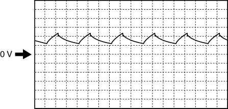
AK |
Shift solenoid E |
TCC released |
Below 1.0 |
|
|
TCC engaged |
B+ |
|||
|
AL |
Shift solenoid C |
(See Shift solenoid C.) |
|
|
|
AM |
Pressure control solenoid B |
(See Pressure control solenoid B.) |
|
|
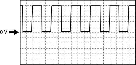
Input/Output Wave From (Reference)
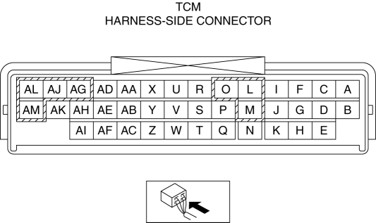
Shift solenoid A
-
TCM terminals
-
AG (+)—body GND (-)
-
Oscilloscope setting
-
5 V/DIV (Y), 5 ms/DIV (X), DC range
-
Test Condition
-
The following conditions are met:
-
Selector lever position: D position
-
Gear position: 4GR
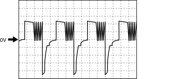
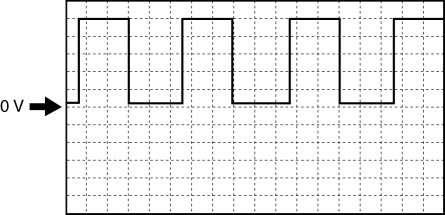
Shift solenoid B
-
TCM terminals
-
AJ (+)—body GND (-)
-
Oscilloscope setting
-
5 V/DIV (Y), 5 ms/DIV (X), DC range
-
Test Condition
-
The following conditions are met:
-
Selector lever position: D position
-
Gear position: 1GR
Shift solenoid C
-
TCM terminals
-
AL (+)—body GND (-)
-
Oscilloscope setting
-
5 V/DIV (Y), 5 ms/DIV (X), DC range
-
Test Condition
-
The following conditions are met:
-
Selector lever position: D position
-
Gear position: 1GR
Pressure control solenoid B
-
TCM terminals
-
AM (+)—body GND (-)
-
Oscilloscope setting
-
5 V/DIV (Y), 5 ms/DIV (X), DC range
-
Test Condition
-
Shifting from 4GR to 5GR or from 5GR to 4GR
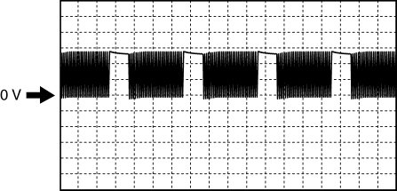
Pressure control solenoid A (+)
-
TCM terminals
-
AD (+)—body GND (-)
-
Oscilloscope setting
-
5 V/DIV (Y), 1 ms/DIV (X), DC range
-
Test Condition
-
The following conditions are met:
-
Switch the ignition to ON (engine off)
-
Selector lever position: P position
-
Accelerator pedal fully depressed
Pressure control solenoid A (-)
-
TCM terminals
-
AE (+)—body GND (-)
-
Oscilloscope setting
-
200 mV/DIV (Y), 1 ms/DIV (X), DC range
-
Test Condition
-
The following conditions are met:
-
Switch the ignition to ON (engine off)
-
Selector lever position: P position
-
Accelerator pedal fully depressed
Input/turbine speed sensor
-
TCM terminals
-
AB (+)—Y (-)
-
Oscilloscope setting
-
1 V/DIV (Y), 2 ms/DIV (X), DC range
-
Test Condition
-
Idle at P position after warm-up
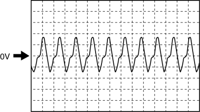
Intermediate sensor
-
TCM terminals
-
AC (+)—body GND (-)
-
Oscilloscope setting
-
1 V/DIV (Y), 200 µs/DIV (X), DC range
-
Test Condition
-
The following conditions are met:
-
Gear position: 3GR
-
Vehicle speed: 30 km/h {19 mph}
VSS
-
TCM terminals
-
Z (+)—body GND (-)
-
Oscilloscope setting
-
1 V/DIV (Y), 2 ms/DIV (X), DC range
-
Test Condition
-
The following conditions are met:
-
Gear position: 3GR
-
Vehicle speed: 30 km/h {19 mph}
 TCM Configuration [Fw6 A EL]
NOTE:
The TCM is built into the control valve body.
1. Verify TCM configuration implementation necessity for replacement parts.
Replacement part
Conf ...
 TCM Removal/Installation [FS5 A EL]
CAUTION:
Do not apply a shock to or touch the projection on the TCM, otherwise it
may not operate normally.
1. Perform the following procedures.
a. Remove the battery cover..
b. D ...
Other materials:
Battery Replacement
If the buttons on the transmitter are
inoperable and the operation indicator
light does not flash, the battery may be
dead.
Replace with a new battery before the
transmitter becomes unusable.
CAUTION
Make sure the battery is installed
correctly. Battery leakage could occur if ...
Electronic key battery
If the electronic key battery of your Subaru Solterra becomes depleted,
it should be replaced promptly to ensure uninterrupted operation of all key functions.
■ If the key battery is depleted
When the battery inside the Subaru Solterra electronic key weakens or fully discharges,
you may noti ...
Fuel Pump Unit Disassembly/Assembly [Mzr 2.0, Mzr 2.5]
WARNING:
Fuel is very flammable liquid. If fuel spills or leaks from the pressurized
fuel system, it will cause serious injury or death and facility breakage. Fuel
can also irritate skin and eyes. To prevent this, always complete the “Fuel
Line Safety Procedure”, while referring ...
