Mazda 3 Service Manual: Valve Clearance Adjustment [Mzr 2.0, Mzr 2.5]
1. Remove the battery cover..
2. Disconnect the negative battery cable.
3. Remove the plug hole plate..
4. Disconnect the wiring harness.
5. Remove the ignition coils..
6. Remove the spark plugs..
7. Remove the ventilation hose.
8. Remove the oil level gauge.
9. Remove the cylinder head cover..
10. Remove the aerodynamic under cover No.2 and splash shield as a single unit..
11. Remove the generator drive belt with the A/C drive belt still installed and set it out of the way. (MZR 2.0).
12. Remove the drive belt. (MZR 2.5).
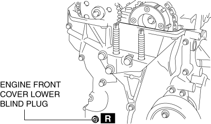
13. Remove the engine front cover lower blind plug.
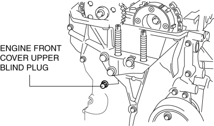
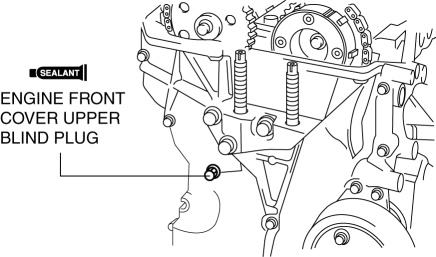
14. Remove the engine front cover upper blind plug.
15. Disconnect the drive shaft (RH) from joint shaft, set the drive shaft (RH) out of the way. (MTX).
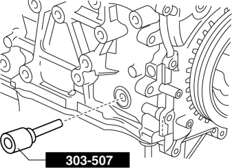
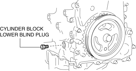
16. Remove the cylinder block lower blind plug, and install the SST.
17. Rotate the crankshaft in the direction of the engine rotation so that the No.1 piston is at top dead center (TDC) of the compression stroke. (Until the counterweight contacts SST
and stops.)
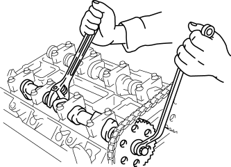
18. Loosen the timing chain using the following procedure.
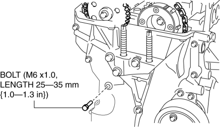
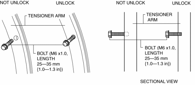
a. Insert a suitable bolt (M6 X 1.0, length 25—35 mm {1.0—1.3 in})
into the engine front cover upper blind plug and tighten it until it contacts the chain tensioner arm, and then rotate it back one turn. (Set the bolt slightly away from the chain tensioner arm so that it does not contact it.)
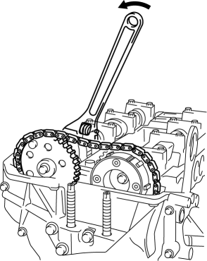
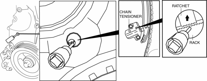
b. Using the cast hexagon on the exhaust camshaft, apply force counterclockwise to facilitate unlocking the chain tensioner ratchet.
c. Using a Hex bit socket (2.5 mm {0.098 in})
or T15 Torx bit socket, unlock the chain tensioner ratchet so that it can be lifted up.
d. Using the cast hexagon on the exhaust camshaft, apply force in the direction of the engine rotation to increase tension on the chain.

NOTE:
-
The chain tensioner rack is compressed using the chain tension generated by applying force to the exhaust camshaft in the direction of the engine rotation.
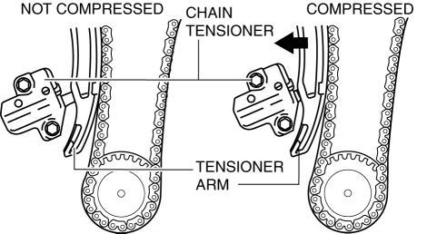
e. Screw in the bolt set in Step 1 approx. 5 mm {0.2 in} and secure the tensioner arm with the rack compressed.
NOTE:
-
The racket has not been unlocked if the bolt cannot be pressed in approx. 5 mm {0.2 in}.
-
If the tensioner arm cannot be secured, return the bolt to its original position and repeat the procedure from Step 3.
19. Fix the exhaust camshaft using a wrench on the cast hexagon, and loosen the camshaft sprocket bolt.
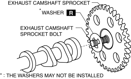
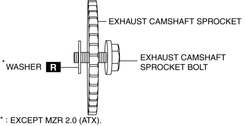
20. Remove the exhaust camshaft sprocket bolt, exhaust camshaft sprocket, and washer (The washers may not be installed.) as a single unit.
CAUTION:
-
Perform the work carefully so that the washer does not drop out. (The washers may not be installed.)
NOTE:
-
The washers do not have to be installed on the MZR 2.0 (ATX) (there is no problem with installing them).
-
Be careful not to install a washer on only the IN or EX side.
21. Remove the OCV..
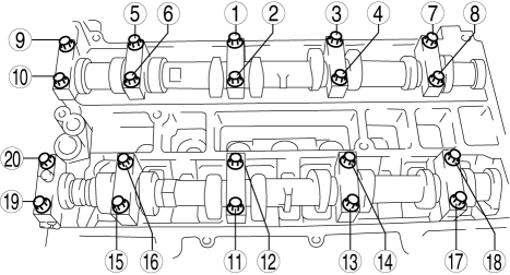
22. Loosen the camshaft cap bolts in two or three steps in the order shown in the figure and remove the camshaft cap.
NOTE:
-
The camshaft caps are to be kept ordered for correct reassembly in their original positions. Do not mix the caps.

23. Remove the camshafts for the intake and exhaust sides.
24. Remove the tappet.
25. Install an appropriate tappet based on the results of the valve clearance inspection.
-
Selected tappet = Removed tappet thickness + Measured valve clearance - Standard valve clearance
-
Valve clearance for inspection [Engine cold]
-
IN: 0.22—0.30 mm {0.009—0.011 in}
-
EX: 0.27—0.37 mm {0.011—0.014 in}
26. Verify that No.1 cylinder is at TDC of the compression stroke. (Position counterweight contacts SST
.)
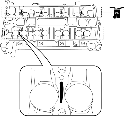
27. Apply the gear oil (SAE No.90 or equivalent) to each journal of the cylinder head as shown in the figure.
28. Install the camshaft with No.1 cylinder aligned with the TDC position.
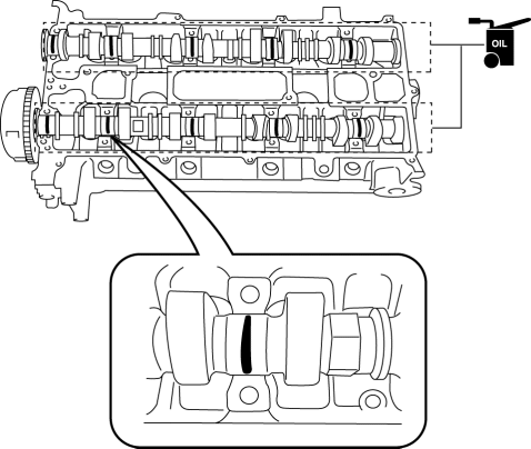
29. Apply the gear oil (SAE No.90 or equivalent) to each journal of the camshaft as shown in the figure.
30. Temporarily tighten the camshaft cap bolts evenly in 2—3 steps.
31. Tighten the camshaft cap bolts in the order shown in the following two steps.
-
Tightening procedure
-
Step 1: 5.0—9.0 N·m {51—91 kgf·cm, 45—79 in·lbf}
-
Step 2: 14—17 N·m {1.5—1.7 kgf·m, 11—12 ft·lbf}
32. Install the OCV..
33. Install the timing chain, exhaust camshaft sprocket bolt, exhaust camshaft sprocket, and a new washer (Except MZR 2.0 (ATX).) as a single unit.
CAUTION:
-
Install a washer to the fourth or fifth thread of the exhaust camshaft sprocket bolt being careful not to drop the washer. (Except MZR 2.0 (ATX).)
-
Do not tighten the camshaft sprocket bolt at this stage. Verify the valve timing before performing the bolt tightening.
NOTE:
-
The washers do not have to be installed on the MZR 2.0 (ATX) (there is no problem with installing them).
-
Be careful not to install a washer on only the IN or EX side.
-
If the washers are not installed, do not install the washers to both the IN and EX sides.
-
If the washers are to be installed, install them on both the IN and EX sides.
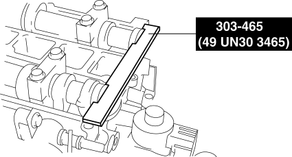
34. Install the SST
on the camshaft as shown in the figure.
35. Remove the installation bolt for the engine front cover upper blind plug (M6 X 1.0 length 25—35mm {1.0—1.3 in})
, and apply tension to the timing chain.
36. Fix the exhaust camshaft using a wrench on the cast hexagon, and tighten the sprocket bolt.
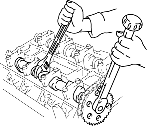
-
Tightening torque
-
69—75 N·m {7.1—7.6 kgf·m, 51—55 ft·lbf}
37. Remove the SST
from the camshaft.
38. Remove the SST
installed in the cylinder block lower blind plug hole.
39. Rotate the crankshaft clockwise two turns and inspect the valve timing.
-
If not aligned, loosen the camshaft sprocket bolt and repeat the procedure from Step 34.
40. Install the cylinder block lower blind plug.
-
Tightening torque
-
18—22 N·m {1.9—2.2 kgf·m, 14—16 ft·lbf}
41. Connect the drive shaft (RH) to joint shaft. (MTX).
42. Apply the silicone sealant and install the engine front cover upper blind plug.
CAUTION:
-
Install the engine front cover upper blind plug before the applied silicone sealant starts to harden.
-
Tightening torque
-
8—11 N·m {82—117 kgf·cm, 71—101 in·lbf}
43. Install a new engine front cover lower blind plug.
-
Tightening torque
-
10—14 N·m {102—142 kgf·cm, 89—123 in·lbf}
44. Install the drive belt. (MZR 2.5).
45. Install the generator drive belt. (MZR 2.0).
46. Install the aerodynamic under cover No.2 and splash shield as a single unit..
47. Install the cylinder head cover..
48. Install the oil level gauge.
49. Install the ventilation hose.
50. Install the spark plugs..
51. Install the ignition coils..
52. Connect the wiring harness.
53. Install the plug hole plate..
54. Connect the negative battery cable..
55. Install the battery cover..
 Cylinder Head Gasket Replacement [Mzr 2.0, Mzr 2.5]
WARNING:
Fuel vapor is hazardous. It can very easily ignite, causing serious injury
and damage. Always keep sparks and flames away from fuel.
Fuel line spills and leakage are danger ...
 Valve Clearance Inspection [Mzr 2.0, Mzr 2.5]
1. Remove the battery cover..
2. Disconnect the negative battery cable..
3. Remove the plug hole plate..
4. Disconnect the wiring harness.
5. Remove the ignition coils..
6. Remove the spark ...
Other materials:
Caliper (Rear) Disassembly/Assembly
1. Disassemble in the order indicated in the table.
1
Dust seal
(See Dust Seal Assembly Note.)
2
Bleeder cap
3
Bleeder screw
4
Caliper body
2. Assemble in the reverse orde ...
Vanity Mirror Illumination Inspection
1. Disconnect the negative battery cable..
2. Remove the sunvisor..
3. Verify that the continuity between the vanity mirror illumination terminals
is as indicated in the table.
If not as indicated in the table, inspect the bulb. If there is no malfunction,
replace the sunvisor.
...
ABS HU/CM Removal/Installation
WARNING:
If the ABS HU/CM configuration is not completed, it could result in an unexpected
accident due to the ABS being inoperative. If the ABS HU/CM or ABS CM is replaced,
always use the automatic configuration function so that the ABS operation conditions
are correct.
CAUTI ...
