Mazda 3 Service Manual: Oil Seal (Differential) Replacement [Fw6 A EL]
1. Remove the aerodynamic under cover No.2 and the splash shield as a single unit..
2. Remove the oil seal.
a. Drain the ATF..
b. Disconnect the drive shaft (LH) from the transaxle..
c. Disconnect the drive shaft (RH) from the joint shaft..
d. Remove the joint shaft..
CAUTION:
-
The oil seal is easily damaged by the sharp edges of the drive shaft splines. Do not let the splines contact the oil seal.
e. Remove the oil seal using a flathead screwdriver.
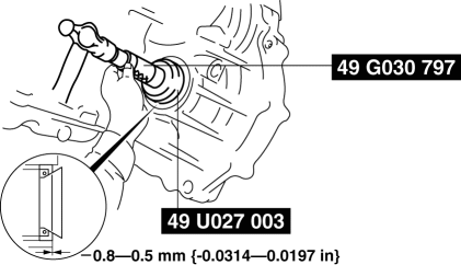
3. Using the SSTs
and a hammer, tap a new oil seal in evenly until the SST
(49 U027 003
) contacts the transaxle case.

4. Coat the lip of the oil seal with ATF.
5. Install the joint shaft..
6. Install the drive shaft (RH) to the joint shaft..
7. Install the drive shaft (LH) to the transaxle..
8. Add the ATF..
9. Install the aerodynamic under cover No.2 and the splash shield as a single unit..
10. Perform the “Mechanical System Test”..
 Oil Seal (Differential) Replacement [C66 M R]
1. Remove the aerodynamic under cover No.2 and the splash shield as a single
unit..
2. Drain the manual transaxle oil..
3. Disconnect the drive shaft (LH) from the MTX..
4. Disconnect the driv ...
 Oil Seal (Differential) Replacement [G35 M R]
1. On level ground, jack up the vehicle and support it evenly on safety stands.
2. Remove the aerodynamic under cover No.2..
3. Drain the oil from the transaxle..
4. Remove the front splash shi ...
Other materials:
Seat Warmer Unit Inspection
WARNING:
Handling a front seat (with built-in side air bag) improperly can accidentally
operate (deploy) the air bag, which may seriously injure you. Read the service
warnings before handling a front seat (with built-in side air bag)..
CAUTION:
After removing a front seat ...
Steering Wheel And Column Inspection
Play Inspection
1. With the wheels in the straight-ahead position, start the engine.
2. Turn the steering wheel to the left and right gently, then verify that the
steering wheel play is within the specification.
Steering wheel play
0—30 mm {0—1.18 in} (When hydraulic operating)
...
Relay Block Inspection [With Advanced Keyless Entry And Push Button Start System]
1. Disconnect the negative battery cable..
2. Remove the following parts:
a. Driver-side front scuff plate.
b. Driver-side front side trim.
c. Hood release lever.
d. Upper panel.
e. Shift knob (MTX)(See MANUAL TRANSAXLE SHIFT MECHANISM REMOVAL/INSTALLATION
[G66M-R].)(See MANUAL TRANSAX ...
