Mazda 3 Owners Manual: Schedule 2
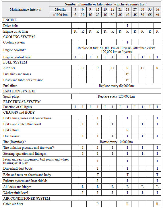
Chart symbols:
I: Inspect: Inspect and clean, repair, adjust, fill up, or replace if
necessary.
R: Replace
L : Lubricate
C: Clean
T: Tighten
Remarks:
*1 Use of FL-22 is recommended when replacing engine coolant. Using engine
coolant other than FL-22 may
cause serious damage to the engine and cooling system.
*2 According to state/provincial and federal regulations, failure to perform maintenance on these items will not void your emissions warranties. However, Mazda recommends that all maintenance services be performed at the recommended time or kilometer period to ensure long-term reliability.
*3 The Tire Pressure Monitoring System (TPMS) initialization must be performed so that the system operates normally (if equipped).
(Cont.)
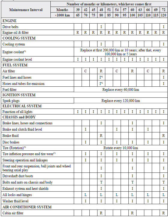
Chart symbols:
I: Inspect: Inspect and clean, repair, adjust, fill up, or replace if
necessary.
R: Replace
L : Lubricate
C: Clean
T: Tighten
Remarks:
*1 Use of FL-22 is recommended when replacing engine coolant. Using engine
coolant other than FL-22 may
cause serious damage to the engine and cooling system.
*2 According to state/provincial and federal regulations, failure to perform maintenance on these items will not void your emissions warranties. However, Mazda recommends that all maintenance services be performed at the recommended time or kilometer period to ensure long-term reliability.
*3 The Tire Pressure Monitoring System (TPMS) initialization must be performed so that the system operates normally (if equipped).
 Schedule 1
Chart symbols:
I: Inspect: Inspect and clean, repair, adjust, fill up, or replace if
necessary.
R: Replace
L : Lubricate
T: Tighten
Remarks:
*1 Use of FL-22 is recommended when replacing e ...

Other materials:
On Board Diagnostic System Simulation Inspection [Fw6 A EL]
1. Connect the M-MDS (IDS) to the DLC-2.
2. After the vehicle is identified, select the following items from the initialization
screen of the IDS.
a. Select “DataLogger”.
b. Select “Modules”.
c. Select “TCM”.
3. Select the simulation items from the PID table.
4. Perform ...
Brake Assist
During emergency braking situations
when it is necessary to depress the brake
pedal with greater force, the brake assist
system provides braking assistance, thus
enhancing braking performance.
When the brake pedal is depressed hard or
depressed more quickly, the brakes apply
more firmly.
N ...
Relay Block Inspection [With Advanced Keyless Entry And Push Button Start System]
1. Disconnect the negative battery cable..
2. Remove the following parts:
a. Driver-side front scuff plate.
b. Driver-side front side trim.
c. Hood release lever.
d. Upper panel.
e. Shift knob (MTX)(See MANUAL TRANSAXLE SHIFT MECHANISM REMOVAL/INSTALLATION
[G66M-R].)(See MANUAL TRANSAX ...
