Mazda 3 Service Manual: A/C Unit Disassembly/Assembly
1. Disassemble in the order indicated in the table.
CAUTION:
-
If a non-specified grease is used, it may result in abnormal noise or improper operation of the links. Apply only the specified grease to each link.
2. Assemble in the reverse order of disassembly.
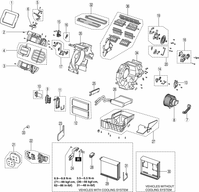
X: Applicable—: Not applicable
|
Step |
Part name |
Disassembly/assembly of main parts |
||
|
Heater core |
Evaporator temperature sensor |
Evaporator |
||
|
1 |
Adhesive polyurethane (1) |
- |
- |
- |
|
2 |
Blower case (1) |
- |
- |
- |
|
3 |
Blower case (2) |
- |
- |
- |
|
4 |
Air intake door |
- |
- |
- |
|
5 |
Air intake link set |
- |
- |
- |
|
6 |
Air intake actuator |
- |
- |
- |
|
7 |
Blower motor pipe |
- |
- |
- |
|
8 |
Blower motor |
- |
- |
- |
|
9 |
Power MOS FET (Full-auto air conditioner) |
- |
- |
- |
|
10 |
Resistor (Manual air conditioner) |
- |
- |
- |
|
11 |
Plate |
- |
X |
X |
|
12 |
Air filter |
- |
X |
X |
|
13 |
Driver-side air mix actuator (Full-auto air conditioner) |
- |
- |
- |
|
14 |
Driver-side air mix link set (Full-auto air conditioner) |
- |
- |
- |
|
15 |
Passenger-side air mix actuator (Full-auto air conditioner) |
- |
- |
- |
|
16 |
Passenger-side air mix link set (Full-auto air conditioner) |
- |
- |
- |
|
17 |
Air mix link set (Manual air conditioner) |
- |
- |
- |
|
18 |
Airflow mode actuator (Full-auto air conditioner) |
- |
- |
- |
|
19 |
Airflow mode link set |
- |
- |
- |
|
20 |
Airflow mode link set (Manual air conditioner) |
- |
- |
- |
|
21 |
Polyurethane foam (1) |
X |
X |
X |
|
22 |
Plate cover |
X |
X |
X |
|
23 |
Adhesive polyurethane (2) (See Adhesive Polyurethane (2) Assembly Note.) |
X |
X |
X |
|
24 |
Evaporator pipe |
X |
X |
X |
|
25 |
Cover |
X |
X |
X |
|
26 |
Heater core |
- |
X |
X |
|
27 |
A/C case (1) |
- |
X |
X |
|
28 |
Expansion valve |
- |
X |
X |
|
29 |
Evaporator |
- |
- |
- |
|
30 |
A/C case (2) |
- |
- |
- |
|
31 |
Evaporator temperature sensor . |
- |
- |
- |
|
32 |
Polyurethane foam (2) |
- |
- |
- |
|
33 |
Bolt |
- |
- |
- |
|
34 |
A/C case (3) |
- |
- |
X |
|
35 |
A/C case (4) |
- |
- |
X |
|
36 |
Door damper |
- |
- |
- |
Evaporator Temperature Sensor Assembly Note
1. Assemble the evaporator temperature sensor as shown in the figure.
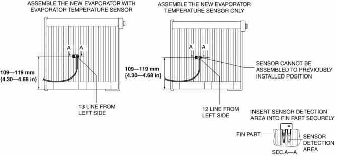
CAUTION:
-
When installing the evaporator temperature sensor without replacing the evaporator, assemble the evaporator temperature sensor with the installation position slid to the left of the previous position by 1 line. If the evaporator temperature sensor is assembled to the previously installed position, it may not function due to poor contact of the fin surface with the sensor detection area caused by fin deformation.
NOTE:
-
Replace the evaporator in which the evaporator temperature sensor cannot be correctly positioned.
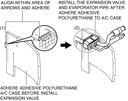
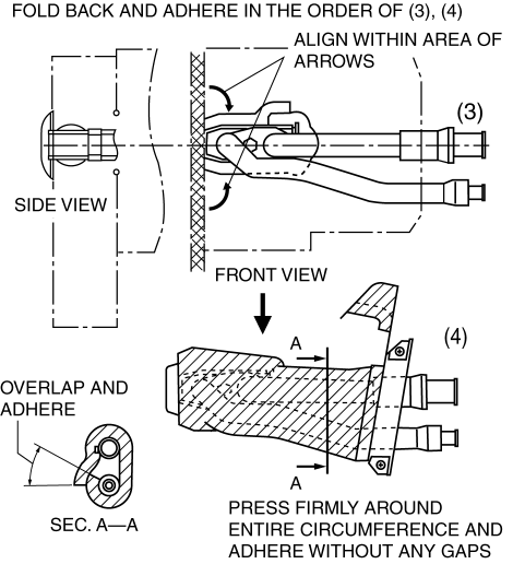
Adhesive Polyurethane (2) Assembly Note
1. Assemble the adhesive polyurethane as shown in the figure.
 A/C Compressor Removal/Installation
1. Disconnect the negative battery cable..
2. Discharge the refrigerant..
3. Remove the aerodynamic under cover No.2..
4. Remove the drive belt..
5. Remove the water hose bracket.
CAUTIO ...
 A/C Unit Removal/Installation
1. Set the air mix mode to MAX COLD.
2. Disconnect the negative battery cable..
3. Discharge the refrigerant..
4. Drain the engine coolant..
5. Remove the plug hole plate.
6. Remove the char ...
Other materials:
Input/Turbine Speed Sensor Inspection [FS5 A EL]
CAUTION:
Water or foreign objects entering the connector can cause a poor connection
or corrosion. Be sure not to drop water or foreign objects on the connector
when disconnecting it.
On-Vehicle Inspection
1. Perform the following procedures.
a. Remove the battery cover..
b. ...
Heated Oxygen Sensor (HO2 S) Removal/Installation [Mzr 2.0, Mzr 2.5]
WARNING:
A hot engine and exhaust system can cause severe burns. Turn off the engine
and wait until they are cool before removing the exhaust system.
1. Remove the battery cover..
2. Disconnect the negative battery cable..
3. Disconnect the HO2S connector.
4. Remove the HO2S u ...
No.7 Bsm Indicator Light Does Not Flash While Under Bsm Indicator Light Flashing
Conditions (With Combination Switch Operation (Turn Signal Switch)) [Blind Spot
Monitoring (Bsm)]
7
BSM indicator light does not flash while under BSM indicator light-flashing
conditions (with combination switch operation (turn signal switch))
Description
The BSM indicator light does not flash or illuminate continuously,
...
