Mazda 3 Service Manual: Antenna Feeder No.5 Inspection
1. Disconnect the negative battery cable..
2. Remove the following parts:
a. Front scuff plate (RH).
b. Front side trim (RH).
c. Rear seat cushion.
d. Rear scuff plate (RH).
e. Tire house trim (RH).
3. Disconnect the antenna feeder No.4.
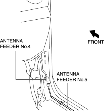
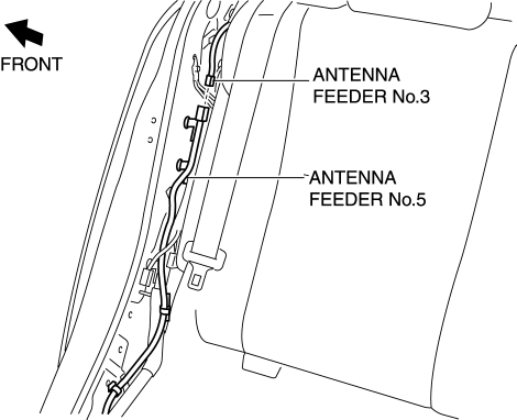
4. Disconnect the antenna feeder No.3.
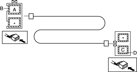
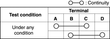
5. Verify that the continuity between antenna feeder No.5 terminals is as indicated in the table.
-
If not as indicated in the table, replace antenna feeder No.5.
 Antenna Feeder No.4 Removal/Installation
Removal
NOTE:
The antenna feeder No.4 is integrated with the dashboard wiring harness.
1. Refer to DASHBOARD DISASSEMBLY/ASSEMBLY.
Installation
CAUTION:
If the antenna feeder ...
 Antenna Feeder No.5 Removal/Installation
1. Disconnect the negative battery cable..
2. Remove the following parts:
a. Front scuff plate (RH).
b. Front side trim (RH).
c. Rear scuff plate (RH).
d. B-pillar lower trim (RH).
e. Rear ...
Other materials:
Passenger Compartment Temperature Sensor Removal/Installation [Full Auto Air
Conditioner]
1. Disconnect the negative battery cable..
2. Remove the following parts:
a. Front scuff plate.
b. Front side trim.
c. Dashboard under cover.
d. Upper panel.
e. Shift lever knob (MTX).
f. Selector lever knob (ATX).
g. Shift panel.
h. Side wall.
i. Console.
j. Hood release lever ...
Interior Light Removal/Installation
1. Disconnect the negative battery cable..
2. Remove the rain sensor cover. (Vehicles with auto light/wiper system).
3. Remove the following parts:
a. Sunroof seaming welt (vehicles with sunroof)
b. A-pillar trim.
c. Front scuff plate.
d. Rear scuff plate.
e. B-pillar lower trim.
f. ...
Fuel Requirements
Vehicles with catalytic converters or oxygen sensors must use ONLY UNLEADED
FUEL,
which will reduce exhaust emissions and keep spark plug fouling to a minimum.
This vehicle will perform best with fuel listed in the table.
* U.S. federal law requires that octane ratings be posted on gasoli ...
