
Mazda 3 Service Manual: Antenna Feeder No.6 Inspection
1. Disconnect the negative battery cable..
2. Remove the following parts:
a. Upper panel.
b. Shift knob (MTX).
c. Selector lever knob (ATX).
d. Shift panel.
e. Side wall.
f. Console.
g. Car-navigation unit.
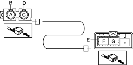
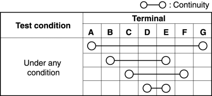
3. Verify that the continuity between antenna feeder No.6 terminals is as indicated in the table.
-
If not as indicated in the table, replace antenna feeder No.6.
 Antenna Feeder No.5 Removal/Installation
1. Disconnect the negative battery cable..
2. Remove the following parts:
a. Front scuff plate (RH).
b. Front side trim (RH).
c. Rear scuff plate (RH).
d. B-pillar lower trim (RH).
e. Rear ...
 Antenna Feeder No.6 Removal/Installation
NOTE:
Antenna feeder No.6 is integrated with the vehicle wiring harness.
1. Refer to CAR-NAVIGATION UNIT REMOVAL/INSTALLATION. ...
Other materials:
Liftgate Adjustment
1. Measure the gap and height difference between the liftgate and the body.
2. Loosen the liftgate hinge installation bolts and adjust the gap by moving
the liftgate.
Standard clearance
a: 5.0―7.0 mm {0.20―0.27 in}
b: -2.0―0 mm {-0.078―0 in}
...
Outside the United States/
Canada
Government regulations in the United States/Canada require that automobiles
meet specific
emission regulations and safety standards. Therefore, vehicles built for use in
the United
States/Canada may differ from those sold in other countries.
The differences may make it difficult or even imp ...
Clock Spring Adjustment
NOTE:
The adjustment procedure is also specified on the caution label of the clock
spring.
1. Set the front wheels straight ahead.
CAUTION:
The clock spring will break if over–wound. Do not forcibly turn the clock
spring.
2. Turn the clock spring clockwise until ...
