Mazda 3 Service Manual: Clock Spring Inspection [Standard Deployment Control System]
1. Disconnect the negative battery cable..
2. Remove the driver–side air bag module..
3. Remove the steering wheel..
4. Remove the column cover.
5. Remove the clock spring..
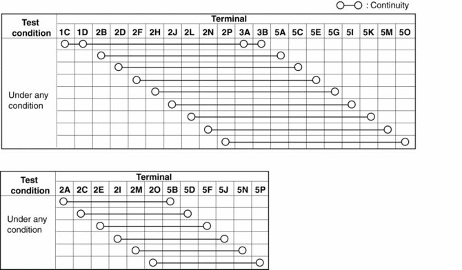
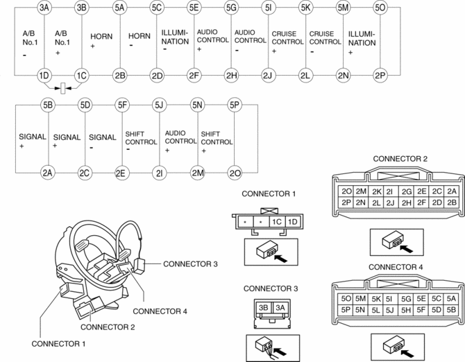
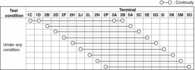
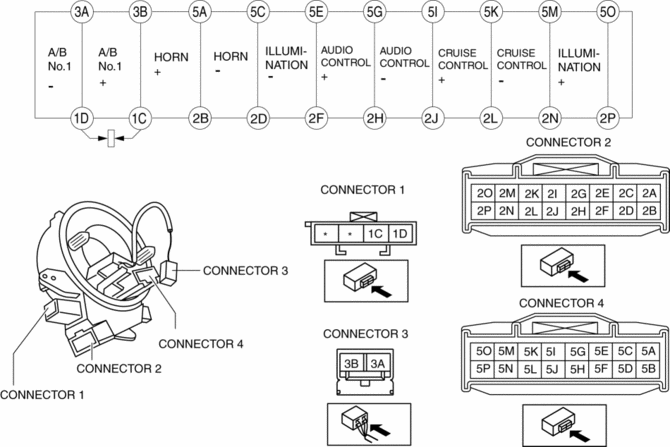
6. Verify that the continuity is as indicated in the table.
-
If not as indicated in the table, replace the clock spring.
NOTE:
-
When the vehicle-side connector for the clock spring is disconnected, terminals 1C and 1D are shorted to prevent unexpected operation (deployment) of the air bag module.
Vehicles with steering switch


Vehicles without steering switch


 Clock Spring Adjustment
NOTE:
The adjustment procedure is also specified on the caution label of the clock
spring.
1. Set the front wheels straight ahead.
CAUTION:
The clock spring will break if ov ...
 Clock Spring Inspection [Two Step Deployment Control System]
1. Disconnect the negative battery cable..
2. Remove the driver–side air bag module..
3. Remove the steering wheel..
4. Remove the column cover.
5. Remove the clock spring..
6. Verify that t ...
Other materials:
Accessory Socket Removal/Installation
Front
1. Disconnect the negative battery cable..
2. Remove the upper panel..
3. Remove the shift lever knob. (MTX).
4. Remove the selector lever knob. (ATX).
5. Remove the shift panel.
6. Remove in the order indicated in the table.
1
Socket
(See Socket Rem ...
Engine Disassembly/Assembly [Mzr 2.0, Mzr 2.5]
1. Remove the engine from the transaxle..
2. Remove the generator..
3. Remove the exhaust system..
4. Remove the EGR valve..
5. Remove the intake-air system..
6. Remove the fuel injectors..
7. Remove the ignition coils..
8. Remove the crankshaft position (CKP) sensor..
9. Disassemble ...
Coolant Reserve Tank Removal/Installation [Mzr 2.0, Mzr 2.5]
WARNING:
Never remove the cooling system cap or loosen the radiator drain plug while
the engine is running, or when the engine and radiator are hot. Scalding engine
coolant and steam may shoot out and cause serious injury. It may also damage
the engine and cooling system.
Tu ...
