
Mazda 3 Service Manual: Condenser Removal/Installation
1. Disconnect the negative battery cable..
2. Discharge the refrigerant..
3. Drain the engine coolant..
4. Remove the air cleaner..
5. Remove the aerodynamic under cover No.2..
6. Remove the aerodynamic under cover No.1..
7. Remove the front bumper..
8. Disconnect the radiator hose from the radiator.
9. Remove the cooling fan component..
10. Remove the radiator..
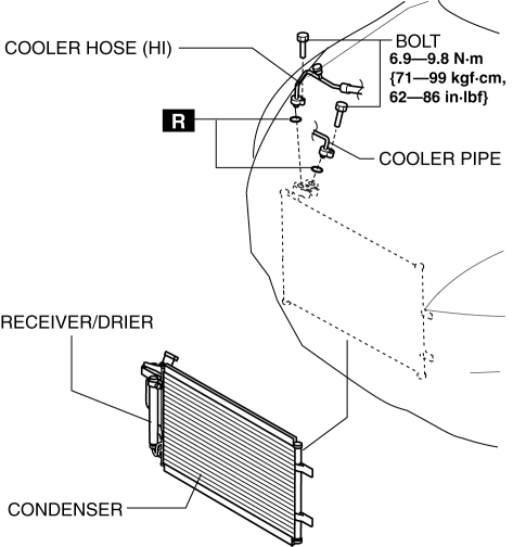
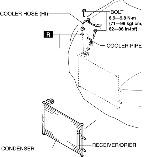
11. Disconnect the cooler hose (HI) and cooler pipe. Do not allow remaining compressor oil in the refrigerant line to spill..
CAUTION:
-
If moisture or foreign material enters the refrigeration cycle, cooling ability will be lowered and abnormal noise or other malfunction could occur. Always plug open fittings immediately after removing any refrigeration cycle parts.
12. Remove the condenser, being careful not to allow remaining compressor oil in the condenser to spill..
MZR 2.0, MZR 2.5, SKYACTIV-G 2.0
MZR 2.3 DISI Turbo
CAUTION:
-
If moisture or foreign material enters the refrigeration cycle, cooling ability will be lowered and abnormal noise or other malfunction could occur. Always plug open fittings immediately after removing any refrigeration cycle parts.
13. Install in the reverse order of removal.
14. Inspect for engine coolant leakage..
15. Perform the refrigerant system performance test..
Condenser Installation Note
1. After replacing the condenser, add compressor oil to the refrigeration cycle.
-
Supplemental oil amount (approx. quantity)
-
20 ml {20 cc, 0.68 fl oz}
 Condenser Inspection
1. Inspect the condenser for cracks, damage, and oil leakage.
If there is any malfunction, replace the condenser.
2. Visually inspect the fins for clogging of foreign material.
I ...
 Drive Belt Inspection [Mzr 2.0, Mzr 2.5]
MZR 2.0
A/C drive belt
NOTE:
Drive belt deflection/tension inspection is not necessary because of the
use of the maintenance-free type A/C drive belt.
Replace the drive belt i ...
Other materials:
Global Positioning System (Gps) Antenna Removal/Installation
With Audio Unit (Without Display)
1. Disconnect the negative battery cable..
2. Remove the following parts:
a. Upper column cover.
b. Instrument cluster.
3. Remove in the order indicated in the table.
1
Connector
2
Screw
...
Pilot Bearing Inspection [G66 M R]
1. Perform the following procedures.
a. Remove the battery cover..
b. Disconnect the negative battery cable.
c. Remove the battery component. (ex: battery, battery tray and PCM component).
d. Remove the air cleaner component..
e. Remove the exhaust manifold insulator installation bolts an ...
Coupler Component Removal/Installation [Fw6 A EL]
WARNING:
A hot transaxle and ATF can cause severe burns. Turn off the engine and wait
until they are cool.
Always wear protective eye wear when using the air compressor. If the air
compressor is used, any particles of dirt or soiling could spatter and get into
the eyes.
...
