Mazda 3 Service Manual: Front Door Latch And Lock Actuator Removal/Installation
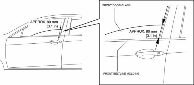
1. To access the glass installation bolt, position the front door glass so that the distance from the top of the front door glass to the upper part of the front beltline molding is approx. 80 mm {3.1 in}
.
2. Disconnect the negative battery cable..
3. Remove the following parts:
a. Inner garnish.
b. Front door trim.
c. Front inner handle.
d. Front door speaker.
e. Front door glass.
f. Front door module panel.
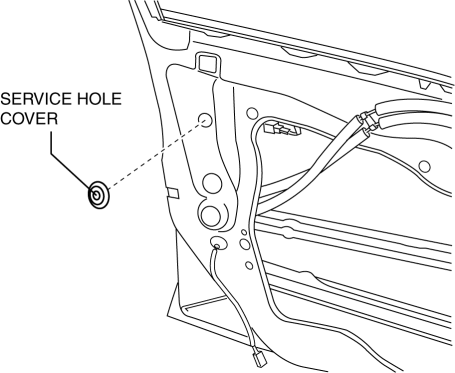
4. Remove the service hole cover (with front door key cylinder).
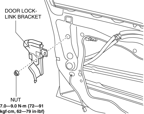
5. Remove the tab, then remove the door lock-link bracket (with front door key cylinder).
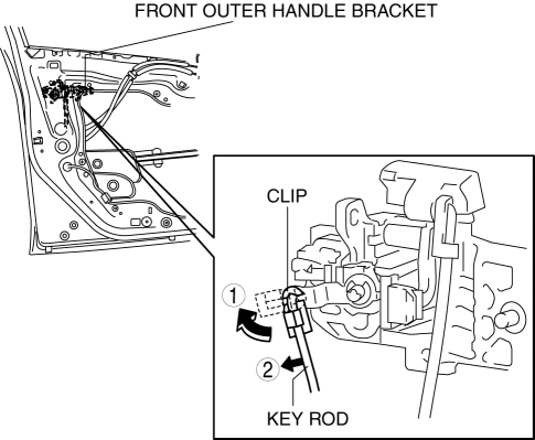
6. Disconnect the key rod from the front outer handle bracket.
7. Remove the screw.
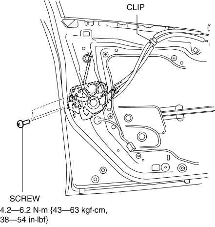
8. Detach the clips.
9. Press down the rod holder of the front door latch and lock actuator in the direction of the arrow.
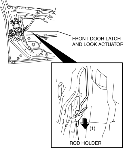
10. Maintaining the condition in Step 9, remove the front door latch and lock actuator.
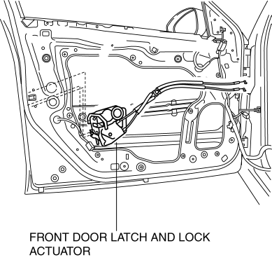
11. Install in the reverse order of removal.
 Front Door Latch And Lock Actuator Inspection
1. The following actuators and switches are integrated with the front door latch
and lock actuator. Inspect the front door latch and lock actuator according to each
inspection procedure for the fo ...
 Front Door Latch Switch Inspection
1. To access the glass installation bolt, position the front door glass so that
the distance from the top of the front door glass to the upper part of the front
beltline molding is approx. 80 mm { ...
Other materials:
Aerodynamic Under Cover No.1 Removal/Installation
1. Remove the aerodynamic under cover No.2..
2. Peel off the front mudguard..
3. Remove the bolts and fastener.
4. Remove the aerodynamic under cover No.1 in the direction of the arrow shown
in the figure.
CAUTION:
Be careful not to damage the aerodynamic under cover No.1 durin ...
Control Valve Body Removal/Installation [FS5 A EL]
Primary Control Valve Body On-Vehicle Removal
WARNING:
A hot transaxle and ATF can cause severe burns. Turn off the engine and wait
until they are cool.
Using compressed air can cause dirt and other particles to fly out, causing
injury to the eyes. Wear protective eyeglasses w ...
Front Door Hinge Removal/Installation
1. Disconnect the negative battery cable..
2. Remove the following parts:
a. Front bumper.
b. Front combination light.
c. Front fender molding.
d. Side step molding.
e. Front fender panel.
f. Front door.
3. Remove in the order indicated in the table.
1
B ...
