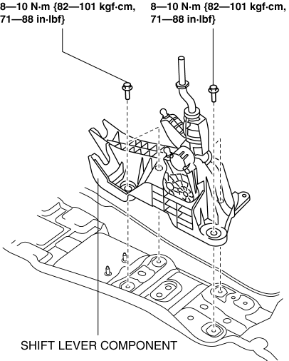
Mazda 3 Service Manual: Manual Transaxle Shift Mechanism Removal/Installation [C66 M R]
1. Remove the battery cover..
2. Disconnect the negative battery cable..
3. Remove the shift lever.
a. Remove the upper panel..
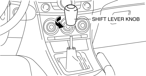
b. Remove the shift lever knob.
c. Remove the shift panel..
d. Remove the side wall..
e. Remove the console..
f. Detach the clip as shown in the figure.
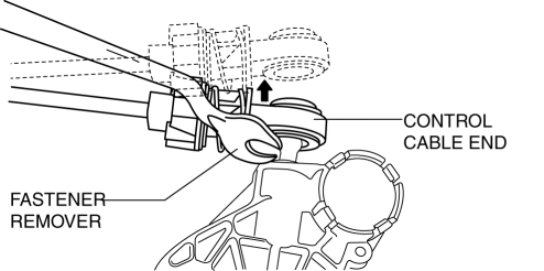
g. Remove the control cable end from shift lever using a fastener remover.
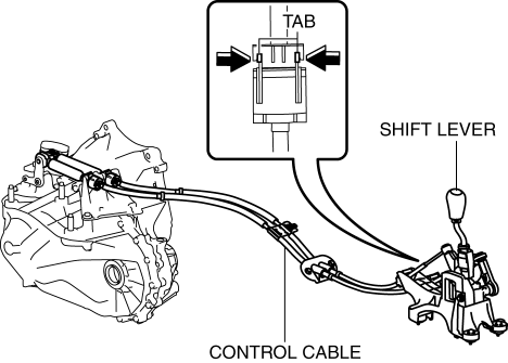
h. Press the tabs on the control cable as shown in the figure and remove the shift lever from the control cable.
i. Remove the shift lever.
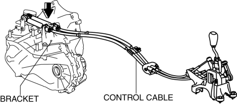
4. Remove the control cable.
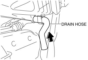
a. Disconnect the drain hose connected to A/C unit.
b. Remove the control cable end from the MTX.
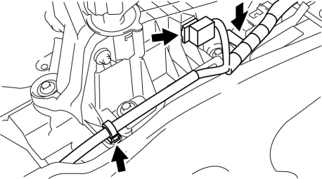
i. Pull the lock pin in the direction of the arrow shown in the figure and release the control cable end (MTX side) lock.
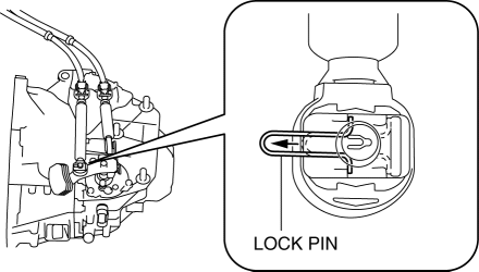
ii. Remove the control cable end from the MTX.
c. Press the tabs on the control cable and disconnect the control cable from the bracket.
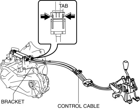
d. Remove the bracket.
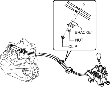
i. Remove the brace bar..
ii. Remove the fastener retaining insulator (front) and set insulator (front) aside..
iii. Remove the fastening nut for the bracket.
iv. Remove the fastening clip for the bracket and remove the bracket.
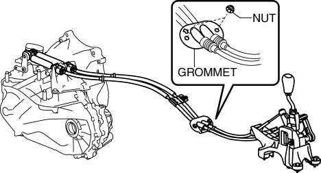
e. Remove the fastening nuts for the grommet.
f. Remove the control cable using two people.
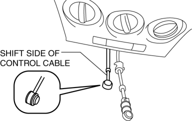
i. While pressing the shift side of the control cable from the cabin, pull it out to the engine compartment.
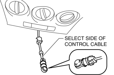
ii. While pressing the select side of the control cable from the cabin, pull it out to the engine compartment.
5. Install the control cable using two people.
a. While pressing the select side of the control cable from the engine compartment, push it in to the cabin.
b. While pressing the shift side of the control cable from the engine compartment, push it in to the cabin.
6. Install the fastening nuts for the grommet.
-
Tightening torque
-
4.0—9.8 N·m {41—99 kgf·cm, 36—86 in·lbf}
7. Install the bracket.
a. Install the bracket and install the fastening clip to the bracket.
b. Install the fastening nut to the bracket.
-
Tightening torque
-
19—25 N·m {2.0—2.5 kgf·m, 15—18 ft·lbf}
c. Install the insulator (front).
d. Install the brace bar.
8. Connect the control cable to the bracket.
9. Install the control cable end to the MTX.
a. Press the lock pin in the direction of the arrow shown in the figure.
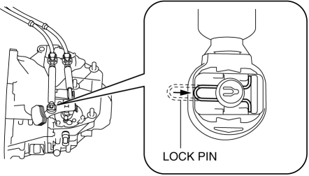
b. Install the control cable end to the MTX.
NOTE:
-
When the connector is engaged, a click sound is heard.
10. Install in the reverse order of removal.
 Manual Transaxle Shift Mechanism Removal/Installation [A26 M R]
1. Remove the battery cover..
2. Disconnect the negative battery cable.
3. Remove the battery and battery tray..
4. Remove the air cleaner and air inlet hose..
5. Remove the aerodynamic under ...
 Manual Transaxle Shift Mechanism Removal/Installation [G35 M R]
1. Remove the battery cover..
2. Disconnect the negative battery cable.
3. Remove the battery component. (ex: battery, battery tray and PCM component).
4. Remove the air cleaner component..
5 ...
Other materials:
Judder Upon Torque Converter Clutch (TCC) Operation [Fw6 A EL]
TROUBLESHOOTING ITEM
Judder upon torque converter clutch (TCC) operation
DESCRIPTION
Vehicle jolts when TCC is engaged.
POSSIBLE CAUSE
Signal malfunction
APP ...
How to use iPod mode (Type A)
An iPod may not be compatible depending
on the model or OS version. In this case,
an error message is displayed.
NOTE
The iPod functions on the iPod cannot
be operated while it is connected to the
unit because the unit controls the iPod
functions.
Playback
Switch the ignition to ACC ...
Non Return Valve Inspection [Mzr 2.0, Mzr 2.5]
WARNING:
Fuel is very flammable liquid. If fuel spills or leaks from the pressurized
fuel system, it will cause serious injury or death and facility breakage. Fuel
can also irritate skin and eyes. To prevent this, always complete the “Fuel
Line Safety Procedure”, while referring ...
